EasyManua.ls Logo

Kenwood KA-727 Service Manual

Kenwood KA-727
12 pages
To Next Page IconTo Next Page
Page #1 background imageLoading...
Page #1 background image
SetVice
MANUAL
KENWOOD
KA-/2/
STEREO
INTEGRATED
AMPLIFIER
Metallic
cabinet
{A01-0699-1
2)
Knob
Panel
ass’y
(K29-1549-04)
x
2
{A20-3982-01)
ot
ya
|
#
Pa
rh
#
et
:
KENWOOD
STERED
a
AMPLE
«
A-
72?
{
i
i
i
Knob
(K29-1550-04)
x
3
Knob
(K27-1207-04)
Phone
jack
Knob
(E11-0111-05)
(K27-1179-03)
Phono
jack
Phono
jack
Phono
jack
(E13-0624-05)
(E13-0818-05)
(E4
3-0496-05)
EA
PEB
ADANTOR
9
6
E|S
Oo
Ole
GO
60
0/0000
<p
©»
7,
GND
(NO8-01
28-35)
Knob Knob
(K27-1180-03)
|
(K27-11
78-03)
Pin
(J12-0094-05)
x
2
Knob
Knob
(K27-1248-13}
(K27-091
7-04)
Knob
(K29-1548-04)
Phono
jack
(E13-0225-05)
Knob
(K27-1176-03)
Knob
Knob
(K27-1177-03)
(K27-1181-04)}
AC
outlet
(EO3-)*
SPEAKERS
(A,8:6~169,A4+B8:12~1692)
rT.
i
-PARLEURS
(AouB:4
~
16
i
162
.Aet8-8
~
NO
UNSWITCHED
SWITCHED
2OOW
MAX.
I
TOTAL
100W
MAX.
=)
cl
i
I]
50
60Hz
AC
power
cord
Lock
terminal
board
(E20-0821-05)
(E30-)*
“Refer
to
Parts
List
on
page
8.
a
ee
re
Question and Answer IconNeed help?

Do you have a question about the Kenwood KA-727 and is the answer not in the manual?

Kenwood KA-727 Specifications

General IconGeneral
TypeIntegrated Amplifier
Frequency Response5Hz to 100kHz
Total Harmonic Distortion0.008% (1kHz)
Input Sensitivity2.5mV (MM), 150mV (line)
Dimensions440 x 109 x 341mm
Weight9.4kg
Damping factor60
Speaker load impedance4Ω to 16Ω
Signal to noise ratio86dB (MM)
Power Output80W per channel into 8Ω (stereo)
Signal-to-Noise Ratio110dB (line)

Summary

Front Panel Overview

Front Panel Components Identification

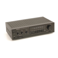
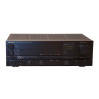
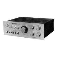
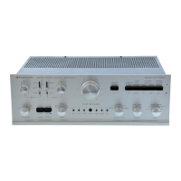
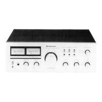
Identifies all knobs, jacks, and indicators on the front panel.

Disassembly for Repair Procedures

Power Amplifier PCB Removal Steps

Details the sequential steps to remove the power amplifier PCB.

Block Diagram and Circuit Description

Signal Flow and Component Functions

Explains the signal path and the function of key components.

Adjustment Procedures

Idle Current Adjustment (Reglages)

Outlines the procedure for setting the idle current.

Alignment Procedures (Abgleich)

Details the steps for audio circuit alignment.

Pre-Amplifier Unit PC Board Layout

Component Side View Diagram

Illustrates the component placement on the pre-amplifier PCB.

Schematic Diagram

Pre-Amplifier and Main Amplifier Circuits

Detailed circuit schematics for amplifier sections.

Technical Specifications

Performance Metrics and Ratings

Covers power output, distortion, frequency response, and input levels.

Main Amplifier Unit PC Board Layout

Component Side View

Diagram showing component placement on the main amplifier PCB.

Modulation Unit PC Board Layout

Component Side View

Diagram showing component placement on the modulation unit PCB.

Schematic Diagram Details

Component Identification and Listings

Lists transistors, diodes, ICs, and other components with part numbers.

Exploded View Diagram

Assembly Breakdown

Visual representation of how the unit is assembled.

Parts List

Component Part Numbers and Descriptions

Comprehensive list of all parts with their respective numbers.

Important Service Notes

Circuit Modification and Safety Precautions

Information on safety critical components and modifications.

Manufacturer and Regional Information

Contact details for Kenwood service centers worldwide.

Related product manuals