Do you have a question about the Kenwood KA-7090R and is the answer not in the manual?
Lists the main sections and accessories of the service manual.
Details the steps for disassembling the unit for servicing and repair.
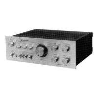
Explains amplifier functions, model variations, and system initialization.
Describes how to enter and utilize diagnostic test modes for troubleshooting.
Covers the microprocessor's block diagram and external connections.
Visual representation of microprocessor pin assignments and functions.
Detailed table of microprocessor pin functions, I/O, and descriptions.
Outlines the essential procedures for adjusting and maintaining the amplifier.
Explains coding systems for capacitors and resistors, including types and values.
Illustrates the unit's assembly with exploded views and lists all parts.
Presents performance specifications, general data, and specific repair tips.
| continuous rated output (DIN/IEC) | 150 W + 150 W |
|---|---|
| rated output (IEC) | 115 W + 115 W |
| output at 4 Ohms | 85 W + 85 W |
| bass tone control | +10 dB (100 Hz) |
|---|---|
| treble tone control | +10 dB (10 kHz) |
| loudness control | +6 dB (100 Hz) |
| phono (MM) input sensitivity/impedance | 2.5 mV/47 kOhm |
|---|---|
| phono (MC) input sensitivity/impedance | 0.2 mV/100 Ohm |
| line input sensitivity/impedance | 200 mV/47 kOhm |
| line frequency response | 5 Hz ~ 100 kHz, +0 dB, -3 dB |
|---|---|
| phono 'RIAA' response | 20 Hz ~ 20 kHz, +0.3 dB, -0.3 dB |
| total harmonic distortion | 0.02 % (20 Hz ~ 20 kHz, 45 W, 8 Ohm) |
| power consumption | 300 W |
|---|---|
| dimensions (W x H x D) | 440 mm x 147 mm x 392 mm |
| weight (net) | 11.7 kg |