EasyManua.ls Logo

Kenwood KDC-MP828 User Manual

Kenwood KDC-MP828
54 pages
To Next Page IconTo Next Page
Page #1 background imageLoading...
Page #1 background image
© 2005-3 PRINTED IN JAPAN
B53-0265-00
(
N
)
1708
CD RECEIVER
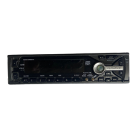
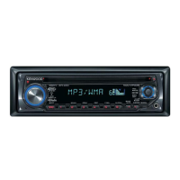
KDC-MP828
KDC-W7531/Y
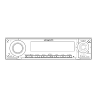
KDC-W8531/Y
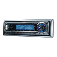
KDC-X789/X8529/X889
SERVICE MANUAL
24Bit DAC
KDC
-
W7531
PTY
FFFF
AN
SCRL
VOLVOL
AUDAUD
AT T
SWSW
AME MENU
SCAN
REP
M
.
RDM
SRC
F.
D
.RDM
S
.MODE
RDM
System
PTY
VOL
AUD
AT T
FFFF
AN
SCRL
SW
SRC
24Bit DAC
KDC
-
W8531
AME
TI
MENU
SCAN
REP
M
.
RDM
F.
D
.RDM
S
.MODE
RDM
System
24Bit DAC
KDC
-
X789
PTY/C.S.
FFFF
AN
SCRL
VOLVOL
AUDAUD
AT T
SW
SCAN
REP
M
.
RDM
SRC
F.
D
.RDM
S
.MODE
RDM
AME
AUTO
MENU
System
VOL
AUD
AT T
FFFF
AN
SCRL
SW
SRC
24Bit DAC
KDC
-
X8529
SCAN
REP
M
.
RDM
F.
D
.RDM
S
.MODE
RDM
System
AME
AUTO
MENU
24Bit DAC
KDC
-
X889
PTY/C.S.
FFFF
AN
SCRL
VOLVOL
AUDAUD
AT T
SWSW
SCAN
REP
M
.
RDM
SRC
F.
D
.RDM
S
.MODE
RDM
AME MENU
AN
KDC
-
MP828
SRC
VOLVOL
AUDAUD
AT T
AME
AUTO
MENU
FFFF
SCANS.MODE
REP
M
.
RDM
F.
SCRL
SWSW
PTY/C.S.
D
.RDM
RDM
AUTO
SPARE TDF PANEL
MAIN UNIT NAME TDF PARTS No. TDF NAME
KDC-MP828 Y33-2200-61 TDF-MP85D
KDC-W7531/Y Y33-2190-64 TDF-W7531
KDC-W8531/Y Y33-2190-63 TDF-W8531
KDC-X789 Y33-2190-61 TDF-75DX
KDC-X8529 Y33-2190-62 TDF-X8529
Mounting hardware assy
(J21-9716-03)
Plastic cabinet assy
(A02-2732-03)
* DC cord
(E30-xxxx-xx)
Lever
(D10-4589-04) x2
* Escutcheon
(B07-xxxx-xx)
KDC-MP828
KDC-W7531/Y
KDC-W8531/Y
KDC-X789
KDC-X8529
KDC-X889
KDC-X889 Y33-2190-60 TDF-85DX
* Tapping screw
(N09-xxxx-xx)
* Antenna adaptor
(T90-0523-05)
* DC cord
(E30-6412-05)
* Compact disc
(W01-xxxx-xx)
* Screw set
(N99-xxxx-xx)
* Remote controller assy (RC-527)
(A70-2067-05)
Battery
(Not supplied)
CD MECHANISM EXTENSION
CORD (24P) : W05-0934-00
A unique identification number (Unique ID) is given to each unit, which is imprinted on
the CD mechanism assembly. If and when the mechanism assembly or Flash ROM
(IC17) on the mechanism board is replaced, it is necessary to write the Unique ID.
For details, refer to “How to Write the Unique ID” on Page 18.
* Depends on the model. Refer to the parts list.
This product uses Lead Free solder.
w
w
w
.
x
i
a
o
y
u
1
6
3
.
c
o
m
Q
Q
3
7
6
3
1
5
1
5
0
9
9
2
8
9
4
2
9
8
T
E
L
1
3
9
4
2
2
9
6
5
1
3
9
9
2
8
9
4
2
9
8
0
5
1
5
1
3
6
7
3
Q
Q
TEL 13942296513 QQ 376315150 892498299
Question and Answer IconNeed help?

Do you have a question about the Kenwood KDC-MP828 and is the answer not in the manual?

Kenwood KDC-MP828 Specifications

General IconGeneral
BrandKenwood
ModelKDC-MP828
CategoryCar Receiver
LanguageEnglish

Summary

BLOCK DIAGRAM

COMPONENTS DESCRIPTION

MICROCOMPUTER TERMINAL DESCRIPTIONS

System Microcomputer: IC102

Detailed terminal functions and processing operations for the system microcomputer.

Panel Microcomputer: IC4

Terminal functions and processing operations for the panel microcomputer.

Mechanism Microcomputer: IC1

Terminal functions and processing operations for the mechanism microcomputer.

TEST MODE OPERATIONS

Test Mode Entry, Exit, and Conditions

Procedures for entering, clearing, and initial conditions of the test mode.

Operational Modes and Checks

Details on tuner modes, CD specs, communication, sensor data, and special displays.

Audio, Menu, Security, and Memory Functions

Operations for audio settings, menus, zones, security, memory, and forced power.

UNIQUE ID WRITING PROCEDURES

Unique ID Introduction and Purpose

Overview of the unique ID, its importance, and identification.

Procedure for Writing Unique ID

Steps to enter write mode and write the unique ID to the mechanism.

Changing Unique ID Contents and Examples

Methods for modifying unique ID digits and viewing examples.

SPECIFICATIONS

EXPLODED VIEWS

CD Mechanism Exploded View

Visual breakdown of the CD mechanism components with part numbers.

Unit Exploded View

Visual breakdown of the main unit components with part numbers.

PARTS LIST

Mechanism Assembly Parts List

List of parts for the CD mechanism assembly.

Related product manuals