EasyManua.ls Logo

Kenwood KR-V6060 Service Manual

Kenwood KR-V6060
52 pages
To Next Page IconTo Next Page
Page #1 background imageLoading...
Page #1 background image
AUDIO-VIDEO
STEREO
RECEIVER
KR-694/v5560/ve060
|
“ENWOOD
SERVICE
MANUAL
©
1994-1
PRINTED
IN
JAPAN
a
2
KR-V5560(KR-694
sames
as
KR-V5560
without
Model
name.)
Knob
Metallic
cabinet
Panel’
Knob
Dressing
plate
Knob
Knob
assy
(K29-5838-04)
(A01-3098-11)
(A60-0526-21)
(K29-5834-13)
(BO3-2887-13)
(K29-5837-02)
(K29-5860-04)
KENWOOD
AUDIO-VIDEO
STEREO
AECEIVER
KR-VSSEO
(REOLE
Knob
Phone
jack’
Knob
Knob
Knob
(K29-5837-02)
(E11-)
(K29-5843-02)
(K29-5866-04)
(K29-5839-14)
Lock
terminal
board
Phono
jack
Slide
switch
=
Phono
jack
=
Miniature
phone
jack
(E20-0476-05)
(€63-0067-15)
x
2
Power
cord
bushing
(S31-3010-05)
(£63-0069-15)
(E11-0188-05)
AC
outlet»
(/42-0083-05)
(E03-)
[KENWOOD
oo
eee
KRVSSEO
AC
TOnON~
CAUTION
‘SEE
CMSTRUCT.ON
MANUAL
FOR
CORRECT
SETTING.
TRASEMARKS
OF
DGIBY
i
LABORATORIES
LICENSING:
ATTENTION
.
ree
LABORATORIES
OUR
OM
PELIAGE
CORRE
a
}
‘SE
AEPORIFA
AL
be
MANUEL
0
INSTRUCTICNS
AUTIGN
[ATTENTION
|
d)
USK
OF
ELLCTARC
SHOCK
|AISGUE
DE
COC
ELECTRIRE:
20
NOT
OPEN
NE
78S
OVA
“6
es
Phono
jack
Foot
Lock
terminal
board
(E63-0068-15)
(J02-0366-15)
x
4
Lock
terminal
board
AC
power
cord*
(E70-0047-05)
(E70-0046-05)
(E30-)
“Refer
to
parts
list
on
page
51.

Other manuals for Kenwood KR-V6060

Question and Answer IconNeed help?

Do you have a question about the Kenwood KR-V6060 and is the answer not in the manual?

Kenwood KR-V6060 Specifications

General IconGeneral
BrandKenwood
ModelKR-V6060
CategoryReceiver
LanguageEnglish

Summary

Accessories

Remote Control Unit

Tuner, CD, and Cassette Controls

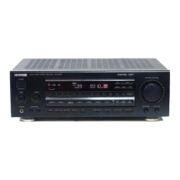
Covers operation keys for tuner, CD player, and cassette deck functions.

Surround and Graphic EQ Controls

Details keys for surround modes and graphic equalizer adjustments.

Power, Volume, and Mute Controls

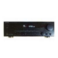
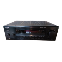
Core controls for receiver power, volume adjustment, and muting.

Input and Monitor Controls

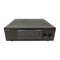
Keys for selecting input sources and monitoring tape playback.

Disassembly for Repair

Front Panel Removal

Instructions for removing the front panel and its associated knobs.

Main Circuit Board Removal

Steps to detach and remove the main circuit board from the chassis.

Block Diagram

Circuit Description

Function Description

Details the available functions and their operation modes for each model variant.

Test Mode

Explains how to enter and use the internal test mode for diagnostic purposes.

Pin Description

Provides detailed descriptions for each pin of the microprocessors, clarifying their function.

Adjustment

FM Section Adjustments

Specific adjustment procedures for the FM tuner section, including discriminator and tuning level.

AM Section Adjustments

Adjustment procedures for the AM tuner section, focusing on tuning level calibration.

Audio Section Adjustments

Procedures for adjusting idle current and noise levels in the audio amplifier stages.

PC Board (Component Side View)

Tuner Unit PC Board Layout

Visual guide to component placement on the tuner unit's circuit board for identification.

Exploded View (Unit)

Parts List

Specifications

Related product manuals