EasyManua.ls Logo

Kenwood KRF-V5030D-S User Manual

Kenwood KRF-V5030D-S
49 pages
To Next Page IconTo Next Page
Page #1 background imageLoading...
Page #1 background image
AUDIO
VIDEO
SURROUND
RECEIVER
Y
KRF-V4530D
KENWOOD
KRF-V5030D/V5030DE/V5030D-S
KRF-V6030D/V6030DE/V6030D-S
VR-405/406/414
SERVICE
MANUAL
eens
Note:
On
circuit
description,
please
refer
to
KRF-V7030D
service
manual(B51-5598-00).
Knob
Front
glass
Panel
(K29-7688-03)
(B10-3550-02)
;
(A60-1757-11)
VOLUME
CONTROL
Sragper
INPUT
SELECTOR
170
SETUP
PUTOOE
——_OIMER
MONITOR
a
i
_——
ewe
|
ff
O
SOUND
LISTEN
MODE
SOURCE
DIRECT
r
y
‘AUTO
EMORY
CICICS
|
=
Sec
aeenae
fn
6CHINPUT
—————————_E
_—CVV/'aVn—_—_—_—
FOR
EXTRA
DIGITAL
AUDIO
FORMAT
Knob
Knob
(K27-2385-04)
(K29-7688-03)
Knob
Knob
Knob
Phone
jack
Knob
(K29-7676-12)
(K29-7682-14)
(K29-7679-04)
(E11-0272-05)
(K29-7685-03)
Pin
jack
Pin
jack
Optical
receiving
module
Power
cord
bushing
AC
power
cord
(E63-1138-05)
(E63-1080-05)
(W02-2716-05)
(J42-0083-05)
(E30-2942-05)
Pin
jack
Pin
jack
Miniature
phone
jack
Metallic
cabinet
(E63-1139-05)
(E63-1141-05)
(E11-0293-05)
(A01-3734-01)
FRONT
SPEAKERS
CENTER
SPEAKERS
REC
)6
-
160)[BIUE}
(8
-
160)
GREEN
FRONT
SPEAKERS
(8-160)
d
=
OGITALIN
|
1
PAWS
ma
Cy
S)-
Ee
(roa)
aE
SSVIES
SD
4
A
erm
O
bu
SURROUND
SPEAKERS
MomTapet
woe
SUS
WOOFER
PRE
OUT
Lock
terminal
board
Pin
jack
Pin
jack
Screw
terminal
board
Lock
terminal
board
(09-0
140-08)
(E20-0321-05)
(E63-1143-05)
(E63-1146-05)
(E70-0049-05)
(E70-0057-05)
70%
Taw
IIlust.
is
KRF-V6030D-S(M).
Question and Answer IconNeed help?

Do you have a question about the Kenwood KRF-V5030D-S and is the answer not in the manual?

Kenwood KRF-V5030D-S Specifications

General IconGeneral
BrandKenwood
ModelKRF-V5030D-S
CategoryReceiver
LanguageEnglish

Summary

Service Manual Overview

Front Panel Controls

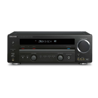
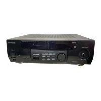
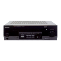
Identifies and labels controls on the front panel of the receiver.

Rear Panel Connections

Details the various input and output jacks and connectors on the rear panel.

Accessories and Cautions

Included Accessories

Lists all included items like remote controls and adapters.

Important Cautions and Notes

Provides critical warnings, memory backup info, and reset procedures.

Controls and Indicators

Receiver Front Panel Controls

Explains the functions of various knobs, buttons, and indicators on the receiver's front panel.

Remote Control Operation

RC-R0509 Remote Control Functions

Details the functions of the RC-R0509 remote control for specific models.

Block Diagram

System Signal Flow Overview

Shows the overall signal flow and component interconnections within the receiver.

Circuit Description

Microprocessor Pin Descriptions

Lists and describes the pins of the main microprocessor (IC1).

Circuit Description Continued

Microprocessor Pin Descriptions (Cont.)

Continues the pin descriptions for the main microprocessor (IC1).

Adjustment Procedures

FM Section Adjustment

Provides step-by-step instructions for adjusting the FM tuner section.

Parts Descriptions

Component Identification Codes

Explains how to read capacitor and resistor codes, including type, value, and tolerance.

PC Board Layout (Component Side)

PC Board Layout (X07-3130-10/X07-3140-10)

Shows the physical placement of components on a specific PC board.

PC Board Layout Continued

PC Board Layout (X07-3130-10 A/3)

Shows component placement for another PC board section.

PC Board Layout Continued

PC Board Component Placement (Page 12)

Continues the visual guide to component placement on the PC boards.

PC Board Layout Continued

PC Board Layout (X08-3010-00 A/3)

Shows component placement for another distinct PC board.

PC Board Layout Continued

PC Board Component Placement (Page 14)

Further illustration of component positioning on the PC boards.

PC Board Layout Continued

PC Board Layout (X14-7120-10 A/6)

Shows component placement for another PC board section.

PC Board Layout Continued

PC Board Component Placement (Page 16)

Final section detailing component layout on the PC boards.

Tuner Unit Circuit Description

Tuner Unit Circuit Details

Details the electronic components and connections within the tuner unit.

Tuner Unit Circuit Description Continued

Tuner Unit Circuit Diagram Section

Continues the explanation of the tuner unit's circuit diagram.

Schematic Diagrams

Schematic Diagram Section (Page 19)

Displays a portion of the overall circuit schematic.

Schematic Diagrams Continued

Schematic Diagram Section (Page 20)

Continues the detailed circuit schematic.

Schematic Diagrams Continued

Schematic Diagram Section (Page 21)

Another part of the comprehensive circuit schematic.

Schematic Diagrams Continued

Schematic Diagram Section (Page 22)

Final section of the circuit schematic diagrams.

Exploded View and Parts List

Unit Assembly Breakdown

Shows the physical breakdown and assembly of the receiver unit.

Parts List

Component Identification (Transistors/ICs)

Lists and identifies various electronic components like transistors and ICs.

Parts List Continued

Component Identification (Diodes/ICs)

Continues the list and identification of electronic components.

Parts List Continued

Component Identification (Resistors)

Further details on component types and their codes.

Parts List Continued

Component Identification (Capacitors)

More component listings and their specifications.

Parts List Continued

Component Identification (ICs/Modules)

Continues the listing of components and related parts.

Parts List Continued

Component Identification (Switches/Connectors)

Lists parts related to switches, connectors, and modules.

Parts List Continued

Component Identification (Resistors/Switches)

Lists resistors and switches with their specifications.

Parts List Continued

Component Identification (Transistors/Diodes)

Lists transistors and diodes with their specifications.

Parts List Continued

Component Identification (ICs/Transistors)

Lists ICs and transistors with their specifications.

Exploded View (Unit)

Unit Assembly Breakdown

Shows the physical breakdown and assembly of the receiver unit.

Parts List

Parts for KRF-V6030D/VR-406

Lists part numbers and descriptions for specific models.

Parts List Continued

Parts for KRF-V5030D/VR-405/414

Lists part numbers and descriptions for other models.

Parts List Continued

Capacitor Parts List

Lists various capacitor types, their values, and part numbers.

Parts List Continued

Connector, Switch, and Module Parts

Lists parts related to connectors, switches, and modules.

Parts List Continued

Resistor Parts (R01-R68)

Lists resistors by part number, description, and wattage.

Parts List Continued

Resistor Parts (R201-R334)

Continues the listing of resistors with their specifications.

Parts List Continued

Diode and IC Parts List

Lists diodes, ICs, and other small electronic components.

Parts List Continued

Transistor and IC Parts List

Lists transistors, ICs, and semiconductor devices.

Parts List Continued

Analogue IC and Transistor Parts

Continues listing analogue ICs and transistors.

Parts List Continued

Resistor and Diode Parts List

Lists resistors and diodes with their specifications.

Parts List Continued

Capacitor and IC Parts List

Lists various capacitors and ICs with their part numbers.

Parts List Continued

Transistor, IC, and Module Parts

Lists transistors, ICs, and special modules like the optical receiver.

Specifications

Audio Specs (USA/Canada)

Details audio performance metrics for US and Canadian models.

Specifications Continued

Tuner and Video Specs

Covers tuner frequencies, sensitivity, and video signal specifications.

Specifications Continued

General Unit Specifications

Includes power consumption, dimensions, and weight of the unit.

Specifications Continued

Audio Specs (Other Countries)

Provides audio performance details for specific models sold outside North America.

Related product manuals