Do you have a question about the Kenwood KT-7020 and is the answer not in the manual?
Lists and describes the purpose of transistors, ICs, and other components in the tuner unit.
Explains the operation of the noise detector and field strength detector circuits.
Details the microprocessor's pin functions, connections, and keymatrix.
Lists functions of various diodes and switches used in the circuit.
Describes programming features, memory functions, and system operating modes like REC CAL and AUTO TUNING.
Illustrates output port logic across different modes and the ATS operation flow.
Lists stored frequencies for band preset scanning in test mode.
Shows the block diagram and terminal descriptions for the PLL frequency synthesizer.
Explains the MPX sub demodulator function and internal circuit.
Details the pin configuration, block diagram, and terminal explanations for the FL driver IC.
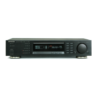
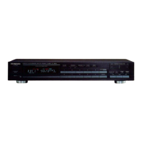
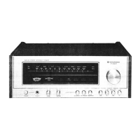
Illustrates the internal and external parts assembly for the M type model.
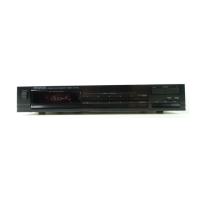
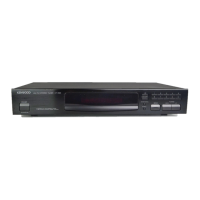
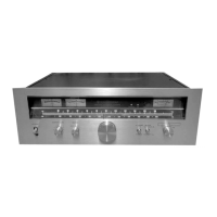
Illustrates the internal and external parts assembly for the E and T type models.
Details performance characteristics for the FM tuner section for different regions.
Details performance characteristics for the AM tuner section.
Lists overall power consumption, dimensions, and weight of the unit.
| tuning frequency range | 87.5 MHz - 108 MHz |
|---|---|
| usable sensitivity (MONO) | 0.95 µV/10.8 dB |
| total harmonic distortion (MONO) | 0.007% |
| signal to noise ratio (MONO) | 92 dB |
| stereo separation (1 kHz) | 65 dB |
| capture ratio | 1.0 dB (WIDE) |
| alternate channel selectivity (+400 kHz) | 60 dB (WIDE) |
| image rejection ratio (at 98 MHz) | 82 dB |
| IF rejection ratio (at 98 MHz) | 110 dB |
| spurious rejection ratio (at 98 MHz) | 105 dB |
| AM suppression ratio | 76 dB |
| frequency response | 20 Hz - 15 kHz, +0.5 dB, -0.5 dB |
| output level/impedance | 0.6 V/3.3 kΩ |
| tuning frequency range | 531 kHz - 1, 602 kHz |
|---|---|
| usable sensitivity | 10 µV (350 µV/m) |
| signal to noise ratio | 55 dB |
| total harmonic distortion | 0.25% |
| image rejection ratio (Loop) | 40 dB |
| selectivity | 30 dB |
| output level/impedance | 0.18 V/3.3 kΩ |
| power consumption | 20 W |
|---|---|
| dimensions (W x H x D) | 440 mm x 98 mm x 318 mm |
| weight | 4.3 kg |