Do you have a question about the Kenwood KX-W6050 and is the answer not in the manual?
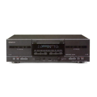
Identifies and describes the function of front panel controls and indicators.
Explains operational modes and switches for recording and playback.
Details the available audio input and output jacks for headphones.
Describes controls specific to Deck A and Deck B operations.
Details the initial steps for disassembling the cassette deck, including removing covers and panels.
Describes the process of removing specific components like the headphone jack and the mechanism assembly.
Details the microprocessor and key integrated circuits for audio amplification and control.
Describes the role of transistors and switches in various circuit functions like muting, bias control, and signal switching.
Explains the function of transistors involved in bias control, grid driving, and output stage switching.
Details components responsible for protection, mute functions, and signal selection.
Explains relay recording, reverse playback, and timer-based operations.
Covers dubbing features, DPSS, CCRS synchronized recording, and serial communication.
Details the pin assignments and functions for the main microprocessor IC.
Provides a detailed description of each pin's function for the main microprocessor.
Continues the detailed pin function descriptions for the main microprocessor.
Explains the test mode for verifying all indicators and mechanical switches.
Describes timed recording and automatic timer playback test modes.
Details automatic timer recording and playback speed switching test modes.
Explains the procedure for testing the dubbing mode functionality.
Illustrates timing diagrams for transitions between stop and record modes (FWD/RVS).
Shows timing charts for FF, RWD, and transitions to STOP from these modes.
Details timing diagrams for playback, CUE, and RVW operations.
Presents an exploded view of the mechanism unit, identifying key components and their assembly.
Explains the belt drive system for motors and specifies torque values for various operations.
Displays detailed illustrations of individual mechanism parts such as gears, arms, and levers.
Details the step-by-step mechanical process for forward playback and recording.
Explains the mechanical sequence for reverse playback and recording operations.
Details the mechanical steps involved in the fast forward function.
Explains the mechanical sequence for the rewind operation.
Describes the mechanism state during fast forward/rewind modes, focusing on pinch roller and play gear.
Details the mechanical actions for stopping playback/record and FF/RWD operations.
Explains the braking mechanism and the steps for CUE/REVIEW operations.
Illustrates the cam gear position when the unit is in STOP mode.
Illustrates the cam gear position during PLAY/REC operations.
Illustrates the cam gear position during FF/RWD operations.
Illustrates the cam gear position during CUE/REVIEW operations.
Details procedures for degaussing, cleaning heads, and adjusting head azimuth.
Covers adjustments for tape speed in double and normal playback modes.
Explains how to adjust playback level, bias current, and record level.
Details adjustments for bias oscillation frequency and bias leakage.
Illustrates the necessary system connections for performing various adjustments.
Details the setup and use of the azimuth adjustment screw for head alignment.
Provides the comprehensive wiring diagram for the main record/playback circuitry.
Shows wiring connections for mechanism units and different model types (K,P,X, T,E, Y,M).
Displays the component layout for the main record/playback amplifier circuit board.
Provides a detailed view of component placement on the amplifier circuit board, including ICs and transistors.
Shows further component placement and identification on the circuit board, including connectors and diodes.
Lists components for the record/playback unit, including cabinets, panels, and accessories.
Lists parts specific to the cassette mechanism assembly, such as dressing plates and instruction manuals.
Details parts for the mechanism and the amplifier unit, including knobs, transformers, and capacitors.
Lists various capacitor types and audio jacks used in the unit.
Lists inductors, resistors, switches, and diodes with their respective part numbers and descriptions.
Details the various diodes and Zener diodes used in the circuit.
Lists remaining diodes, integrated circuits (ICs), and transistors with their part numbers.
Lists additional transistors and major mechanical assembly parts like head base and reel desks.
Lists various mechanical components such as arms, springs, gears, and washers.
Lists the remaining mechanical parts including washers, switches, solenoids, and motor assemblies.
Details specifications for track system, recording, heads, motors, wow/flutter, and fast winding time.
Lists frequency response, signal-to-noise ratio, harmonic distortion, and input/output levels.
| power consumption | 25 W |
|---|---|
| AC bias frequency | 105 kHz |
| wow and flutter IEC | 0.18% |
|---|---|
| wow and flutter DIN | 0.3% |
| wow and flutter W.RMS | 0.09% |
| normal tape frequency response | 25 Hz to 16, 000 Hz, +3 dB |
|---|---|
| CrO2 tape frequency response | 25 Hz to 17, 000 Hz, +3 dB |
| metal tape frequency response | 25 Hz to 18, 000 Hz, +3 dB |
| Dolby NR OFF | 52 dB |
|---|---|
| Dolby B NR ON | 68 dB |
| Dolby C NR ON | 74 dB |
| width | 440 mm |
|---|---|
| height | 137 mm |
| depth | 269 mm |
| weight | 4.7 kg |