EasyManua.ls Logo

Kenwood NV-301 User Manual

Kenwood NV-301
41 pages
To Next Page IconTo Next Page
Page #1 background imageLoading...
Page #1 background image
70%
In compliance with Federal Regulations, following are repro-
duction of labels on, or inside the porduct relating to laser
product safety.
KENWOOD-Crop. certifies this equipment conforms to DHHS
Regulations No.21 CFR 1040. 10, Chapter 1, subchapter J.
DANGER : Laser radiation when open and interlock defeat-
ed.
AVOID DIRECT EXPOSURE TO BEAM.
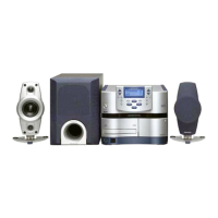
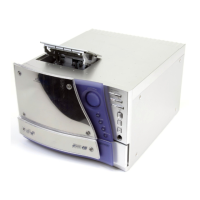
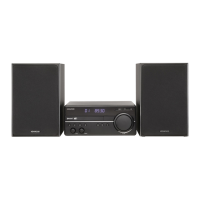
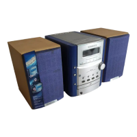
Hi-Fi COMPONENT SYSTEM
RXD-NV301/NV301E/NV701/NV701E
SERVICE MANUAL
© 2000-8/B51-5657-00 (K/K) 3673
V
O
L
U
M
E
C
O
N
T
R
O
L
HI-FI COMPONENT SYSTEM
CD
MULTI CONTROL
SET ENTER
MENU
DEMO
DISC SKIP
OPEN/CLOSE
PHONES
STANDBY
ON/STANDBY
TUNER
TAPE
MD/DVD
BAND
changer
(NV-301/301E/701/701E)
Button
(K29-7904-08)
Knob
(K29-7901-08)
Button
(k29-7903-08)
Button
(K29-7902-08)
Panel(FRONT) *
(A21-)
Figure is RXD-701.
* Refer to parts list on page41.
Panel(FG)
(B10-3642-08)
Panel
(A21-3916-08)
Cover(TRAY)
(A60-1971-08)
Panel
(A21-3911-08)
Panel *
(A21-)
Foot ass'y
(J02-1506-08)x4
w
w
w
.
x
i
a
o
y
u
1
6
3
.
c
o
m
Q
Q
3
7
6
3
1
5
1
5
0
9
9
2
8
9
4
2
9
8
T
E
L
1
3
9
4
2
2
9
6
5
1
3
9
9
2
8
9
4
2
9
8
0
5
1
5
1
3
6
7
3
Q
Q
TEL 13942296513 QQ 376315150 892498299
Question and Answer IconNeed help?

Do you have a question about the Kenwood NV-301 and is the answer not in the manual?

Kenwood NV-301 Specifications

General IconGeneral
CD PlayerYes
USB PortNo
FM TunerYes
AM TunerYes
BluetoothNo
Tuner BandsFM, AM
Total Harmonic Distortion10%
Speaker Impedance6 ohms
Power Output30W per channel

Summary

Contents, Accessories, and Cautions

Contents Overview

Lists main sections and their corresponding page numbers.

Included Accessories

Lists all accessories provided with the audio system.

General Cautions

Provides important warnings and operational advice.

External View and Component Identification

RXD-NV701 Rear Panel Connections

Identifies rear panel ports and modules for the RXD-NV701 model.

RXD-NV301 Rear Panel Connections

Identifies rear panel ports and modules for the RXD-NV301 model.

Disassembly for Repair Procedures

Front Panel Removal Steps

Step-by-step guide on how to remove the front panel of the unit.

Bottom Plate Screw Removal

Instruction to remove screws from the bottom plate during disassembly.

Component Screw Removal Steps

Instruction to remove specific screws for further disassembly.

Disassembly for Repair Procedures (Continued)

Front Panel Connector Removal

Details connector removal for separating the front panel assembly.

CD Mechanism Removal Steps

Steps required to remove the CD mechanism unit.

Circuit Description

Microprocessor IC2 Pin Description

Detailed pinout and function description for microprocessor IC2.

Circuit Description (Continued)

Microprocessor IC2 Pin Description (Continued)

Further pinout details for microprocessor IC2.

YSS912(IC603) Pin Description (NV701)

Pinout for the YSS912 IC used in NV701 models.

Circuit Description (Continued)

Microprocessor IC2 Pin Description (Continued)

Additional pinout details for microprocessor IC2.

YSS912(IC603) Pin Description (NV701) (Continued)

Continues pinout details for the YSS912 IC.

Circuit Description (Continued)

FL Driver IC CXP82832(IC101) Pin Description

Pinout and function description for the FL driver IC.

Key Matrix Mapping

Maps input voltages to control keys for operation.

Adjustment Procedures

Cassette Mechanism Head Adjustments

Procedures for adjusting cassette heads and performing cleaning.

PC Board Adjustment Procedures

Steps for adjusting cassette tape speed and playback level.

PC Board Signal and Bias Adjustments

Adjustments for signal current and bias current on the PC board.

Adjustment Procedures (Continued)

NV701 Measurement Equipment Setup

Equipment connections for NV701 adjustment procedures.

NV301 Measurement Equipment Setup

Equipment connections for NV301 adjustment procedures.

Wiring Diagram

CD, Part, Main, Input Board Wiring

Shows wiring between CD, Part, Main, and Input boards.

Internal Board Wiring

Wiring for Front, Deck, Tuner, and Headphone boards.

Power and Voltage Selector Wiring

Wiring for power transformers and voltage selector boards.

Wiring Diagram (Continued)

Major Board and Speaker Wiring

Wiring diagram for primary internal boards and speaker outputs.

Power Supply and Regional Wiring

Wiring details for power supply boards and regional variants.

PC BOARD (Component side view): RXD-NV701

Input Board Component Layout

Component placement diagram for the Input Board.

Surround Board Component Layout

Component placement diagram for the Surround Board.

PC BOARD (Component side view)

Front-2 Board Component Layout

Component placement diagram for the Front-2 Board.

Front-1 Board Component Layout

Component placement diagram for the Front-1 Board.

Deck Board Component Layout

Component placement diagram for the Deck Board.

CD Board Component Layout

Component placement diagram for the CD Board.

PC BOARD (Component side view): RXD-NV701

Main Board Component Layout

Component placement diagram for the Main Board.

Headphone Board Component Layout

Component placement diagram for the Headphone Board.

Input Board Component Layout

Component placement diagram for the Input Board.

Voltage Selector Sub Board Layout

Component placement diagram for Voltage Selector Sub Board.

Voltage Selector Main Board Layout

Component placement diagram for Voltage Selector Main Board.

Speaker Board Component Layout

Component placement diagram for the Speaker Board.

PC BOARD (Component side view): RXD-NV301

Main Board Component Layout

Component placement diagram for the Main Board.

Headphone Board Component Layout

Component placement diagram for the Headphone Board.

Input Board Component Layout

Component placement diagram for the Input Board.

Voltage Selector Sub Board Layout

Component placement diagram for Voltage Selector Sub Board.

Voltage Selector Main Board Layout

Component placement diagram for Voltage Selector Main Board.

5V Reg Board Component Layout

Component placement diagram for the 5V Reg Board.

Speaker Board Component Layout

Component placement diagram for the Speaker Board.

Exploded View of CD Mechanism

CD Mechanism Exploded View

Exploded diagram of the CD mechanism with part labels.

Exploded View of the Unit

Unit Exploded View

Exploded diagram of the main unit with part labels.

Parts List

RXD-NV301/NV301E/NV701/NV701E Parts

Comprehensive list of parts for all models.

Model Destination Abbreviations

Key to abbreviations for production destinations by model.

Parts List (Continued)

Main Board (RXD-NV701) Components

Detailed parts list for the RXD-NV701 Main Board.

Parts List (Continued)

Main Board (RXD-NV701) Components (Continued)

Continues the parts list for the RXD-NV701 Main Board.

Parts List (Continued)

Resistor and Capacitor Lists

Lists various resistors and capacitors with part numbers.

Parts List (Continued)

Input/Surround Board (RXD-NV701) Components

Detailed parts list for the RXD-NV701 Input/Surround Board.

Parts List (Continued)

Front Board Components

Detailed parts list for the Front Board.

Parts List (Continued)

Front Board Components (Continued)

Continues the parts list for the Front Board.

Parts List (Continued)

Deck Board Components

Detailed parts list for the Deck Board.

Parts List (Continued)

CD Board Components

Detailed parts list for the CD Board.

Parts List (Continued)

General Component Listing

Continues the listing of various components.

Specifications

NV-701 Amplifier Specifications

Technical specifications for the NV-701 amplifier section.

Cassette Deck Specifications

Technical specifications for the cassette deck.

CD Player Specifications

Technical specifications for the CD player.

Tuner Section Specifications

Technical specifications for the tuner section.

General Specifications

Overall specifications including power consumption and dimensions.

Specifications (Continued)

NV-301 Amplifier Specifications

Technical specifications for the NV-301 amplifier section.

Tuner Section Specifications

Technical specifications for the tuner section.

General Specifications

Overall specifications including power consumption and dimensions.

Specification Notes

Notes regarding development policy and performance conditions.

Related product manuals