Do you have a question about the Kenwood NX-320 Series and is the answer not in the manual?
| Operating Temperature | -30°C to +60°C |
|---|---|
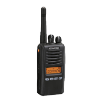
| Frequency Range | 136-174 MHz, 400-470 MHz |
| Power Output | 5 W (VHF), 4 W (UHF) |
| Water Resistance | IP55 |
| Channel Spacing | 6.25 kHz, 12.5 kHz, 25 kHz |
| Digital Protocol | NXDN |
| IP Rating | IP55 |
Recommended precautions for user safety during operation and servicing.
Procedures for using Panel Test and Tuning Modes for adjustments.
Details on PC Mode, programming interfaces, and software requirements.
Explanation of IF, audio amplifier, squelch, and transmitter systems.
Explains amplifiers, PLL, and the ASIC/Memory circuit functions.
Describes LCD, key detection, battery, DSP, power supply, and signaling circuits.
Lists required equipment and outlines radio check procedures.
Procedures for adjusting transmitter power, balance, and deviations.
Procedures for adjusting receiver sensitivity, RSSI, squelch, and signal levels.
Covers Panel Tuning Mode, frequency, and signaling adjustments for E/E2 models.
Tables detailing adjustment items, ranges, and flowcharts for E type calibration.
Covers equipment, radio checks, and transmitter adjustments like Receive/Transmit Assist and Frequency.
Procedures for receiver adjustments including AF level, sensitivity, RSSI, squelch, and low signal levels.
Covers receiver sensitivity, selectivity, distortion, and transmitter power, noise, and modulation specs.