Do you have a question about the Kenwood NX-5900 and is the answer not in the manual?
Guides the user through the initial system setup and configuration.
Covers communication and programming via PC.
Details procedures for updating the transceiver's flash memory firmware.
Details the installation and connection of the optional ignition sense cable.
Details installation of the secure cryptographic module and its associated settings.
Describes the RF, IF, and audio amplifier circuits within the receiver.
Explains the audio, baseband, drive, final amplifier, and APC circuits in the transmitter.
Details the MPU, memory, LCD, and key detection circuits responsible for system control.
Details the ICs and transistors found on the main unit's PCB.
Important safety warnings and precautions before starting disassembly.
Guide for correctly reassembling the main PCB into the chassis.
Details the features and key operations available in the panel test mode.
Explains how to enter and use the panel tuning mode for adjusting transceiver parameters.
Details the procedure for checking the transceiver's high power output in the 700MHz band.
Procedure for checking low power output in the 700MHz band.
Procedure for adjusting the receive assist level, including automatic and manual methods.
Procedure for adjusting maximum deviation for analog wide 5k mode.
Guide for diagnosing faults related to Ball Grid Array Integrated Circuits.
Flowchart for diagnosing and resolving GPS function failures.
Provides an exploded view of the transceiver, identifying major assemblies and parts.
Lists integrated circuits, transistors, and diodes for the main unit.
| Brand | Kenwood |
|---|---|
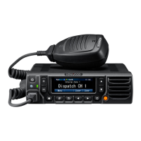
| Model | NX-5900 |
| Category | Transceiver |
| Language | English |