EasyManua.ls Logo

Kenwood PC-1A - User Manual

Kenwood PC-1A
7 pages
Print Icon
To Next Page IconTo Next Page
Loading...
Q«ENwoop
PHONE
PATCH
CONTROLLER
PC-1A
INSTRUCTION
MANUAL
"Your
new
:PC-1A
Phone
Patch
has
been
carefully
engineered
and
manufactured
under
rigid
quality
standards,
and
should
give
you
satisfactory
and
dependable
operation
for
many
years.
|
Before
using,
we
suggest
that
you
read
through
this
instruction
manual
to
become
acquainted
with
correct
operation.
`
Should
any
trouble
arise
with
the
unit,
please
contact
either
your
dealer,
or
the
KENWOOD
factory
service
facility.
FEATURES:
1.
The
PC-1A
Phone
Patch
provides
connection
between
a
transceiver
and
a
telephone
line.
2.
It
is
designed
to
provide
excellent
performance
with
high.
isolation
."
between
receiver
input
and
transmitter.
output.
..
3.
Its
compact
design
permits
convenient
installation
in
a
limited
space.
NOTE:
When
using
the
PC-1A
Phone
Patch
with
a
TS-930,
TS-820,
or
TS-520
series
transceiver,
DO
NOT
use
the
Phone
Patch
IN
or
OUT
jacks
on
the
transceiver.
`
Rather,
follow
the
hookup
instructions
in
this
manual.
THIS
UNIT
COMPLIES
WITH
PART
68,
OF
FCC
RULES.
FCC
REGISTRATION
NUMBER
ALHOTK-70306-OT-N
RINGER
EQUIVALENCE
22А
MANUFACTURED
BY:
TRIO-KENWOOD
COMMUNICATIONS,
INC..
1111
West
Walnut
Street
Ċompton,
California
90220
Scanned
by
Ward
Willats
KG6HAF
Felton,
California
23
August
2002
Question and Answer IconNeed help?

Do you have a question about the Kenwood PC-1A and is the answer not in the manual?

Summary

Kenwood PC-1 A Phone Patch Controller Overview

Introduction and Key Features

General welcome text and a list of the main functional benefits of the PC-1A.

FCC Compliance and Manufacturer Information

Details regarding FCC registration number, ringer equivalence, and manufacturing origin.

Regulatory Responsibilities and Usage Guidelines

FCC Rules for Phone Patch Use by Amateurs

Explains FCC regulations concerning amateur radio operators using phone patches.

Installation Requirements

Steps required for proper installation, including notifying the telephone company.

Important Rules for Phone Patch Operation

Key operating procedures and precautions to ensure correct phone patch usage.

PC-1 A Preparation, Controls, and Connection

Accessories and Required Cables

Lists the standard accessories included with the unit and necessary connecting cables.

Front and Rear Panel Controls

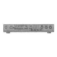
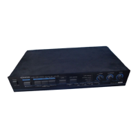
Detailed description of all front and rear panel controls and their functions.

Typical Transceiver Hookup Diagram

Illustrates the standard connection method between the PC-1A and a transceiver.

PC-1 A Wiring and Cable Connector Guide

8-Pin Cable Connector Wiring

Details the pin functions, colors, and wiring for the 8-pin microphone connector.

4-Pin Connector Modification

Explains changing 8-pin to 4-pin for microphone connections to compatible transceivers.

Microphone Connector Wiring

Describes how to change microphone connectors for compatibility.

PC-1 A Operation, Service, and Specifications

Operating Procedures

Step-by-step guide for using the phone patch, including NULL and GAIN adjustments.

Service and Repair Information

Instructions for returning the unit for repair and warranty claims.

Technical Specifications

Key performance metrics, including impedance levels for various connections.

PC-1 A Circuit Diagram

Kenwood PC-1A Specifications

General IconGeneral
BrandKenwood
ModelPC-1A
CategoryController
LanguageEnglish

Related product manuals