Do you have a question about the Kenwood pds20-18 and is the answer not in the manual?
Adherence to safety precautions for qualified personnel during servicing to avoid electric shock.
Specifications for voltage/current regulation, ripple noise, transient response, and accuracy.
Description of circuits within the control unit: DAC, CV/CC, Monitor, Alarm, and Others.
Description of circuits within the power unit: control, current detection, bleeder, and alarm circuits.
Description of circuits within the CPU unit: CPU, switches, ports, display drivers, and optional boards.
Description of circuits within the mother unit: rectifiers, switchers, control, detectors, and main switch.
Description of circuits within the AC unit: filters, rectifiers, switching, control, protection, and detectors.
Steps for adjusting Voltage REF Offset, REF Gain, and Monitor Offset/Gain.
Steps for adjusting Current Ref Offset, Ref Gain, Monitor Offset/Gain.
Procedure for adjusting the Over Voltage Protect (OVP) setting.
| Brand | Kenwood |
|---|---|
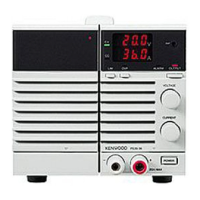
| Model | pds20-18 |
| Category | Power Supply |
| Language | English |