Do you have a question about the Kenwood PS Series and is the answer not in the manual?
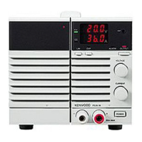
Details the front panel layout and controls of the PS Series power supply.
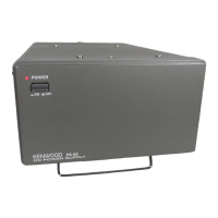
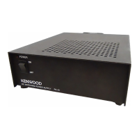
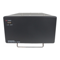
Explains the rear panel layout, including connectors and switches for the PS Series.
Instructions for safely connecting the power cord to the PS Series unit.
Guidance on connecting external loads to the main output terminals of the PS Series.
Procedure for setting the desired voltage and current levels using front panel controls.
How to configure the Over-Voltage Protection (OVP) setting for the PS Series.
Steps to manually turn the output voltage on and off using the front panel controls.
Configuration for enabling automatic output activation upon powering on the PS Series.
Instructions for safely removing the protective grill from the PS Series unit.
Detailed steps for assembling the 20-pin connector for remote control.
Information regarding the 8-pin control connector for rear panel connections.
How to control output voltage using an external voltage source.
Method for adjusting output voltage using an external resistor (Method 1).
Method for adjusting output voltage using an external resistor (Method 2).
How to control output current using an external voltage source.
Method for adjusting output current using an external resistor.
Explains the function to compensate for voltage drop in remote sensing applications.
Procedure for controlling the main relay remotely using an external switch.
Procedure for controlling the output on/off remotely using an external switch.
How to monitor output voltage and current levels using external meters.
How to monitor alarm signals indicating an error or abnormal condition.
How to monitor other status signals like CV, CC, and relay status.
Steps to reset the Over-Voltage Protection (OVP) feature after it has activated.
Procedure to reset the unit after an alarm condition has occurred.
Describes how to connect multiple PS Series units in series for higher voltage output.
Guidance on using the PS Series for charging batteries, including safety precautions.
| Category | Power Supply |
|---|---|
| Manufacturer | Kenwood |
| Input Frequency | 50/60 Hz |
| Dimensions | Varies by model |
| Weight | Varies by model |
| Output Voltage | Adjustable |
| Line Regulation | ≤0.01% + 3mV |
| Load Regulation | ≤ 0.01% + 3 mV |
| Ripple and Noise | ≤1mVrms |
| Display | Digital LED |
| Model | PS Series |
| Protection | overvoltage, overtemperature |
| Input Voltage | 100/110/120/220/230/240 VAC (depending on the model and region) |