EasyManua.ls Logo

Kenwood PS-511S - User Manual

Kenwood PS-511S
8 pages
Print Icon
To Next Page IconTo Next Page
Loading...
^
K
E
N
W
O
OD
Model
PS-511S
OPERATING
MANUAL
Question and Answer IconNeed help?

Do you have a question about the Kenwood PS-511S and is the answer not in the manual?

Overview

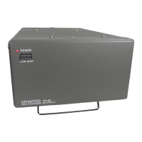
The Kenwood PS-511S is a high-stability power supply designed specifically for use with the TS-511S transceiver. It integrates a communication speaker, a silicon rectifier for high tension voltage, and a voltage regulator.

Technical Specifications:

Output:

The power supply provides various DC and AC outputs, with values measured at the TS-511S connector when the transceiver is in transmit mode (170 watts output, CW mode). Values in parentheses are for receive mode (CW mode).

  • 900V DC: 840V (970V) at 390mA (0.6mA)
  • 300V DC: 300V (310V) at 49mA (6mA)
  • 190V DC: 195V (200V) at 5mA (0.05mA)
  • 150V DC: 150V (150V) at 52mA (85mA)
  • -C DC: -90V (-90V) at 13mA (15mA)
  • 12.6V (a) AC: 13.6V at 2.3A
  • 12.6V (b) AC: 13.8V at 2.2A

Speaker Section:

  • Diameter: 3-17/32" x 5-1/2" (Ellipsoidal)
  • Impedance: 8 ohms
  • Frequency response: 150-5,000 Hz
  • Rated input: 1.5 watts (max.)

General Specifications:

  • Power Requirement: 117 Vac 50/60 Hz, 550 watts (max.)
  • Size: 7-7/8" wide x 6-11/16" high x 13-6/8" deep (Excluding feet)
  • Weight: 26.4 lbs.

Circuit Description:

  • AC Line: An AC type filter is installed to prevent unwanted radiation of radio waves from the AC power line.
  • 900 V Line: This high voltage is obtained from a voltage-doubling rectifier. Two silicon diodes in series ensure the required withstand voltage, with parallel resistors and electrolytic capacitors preventing overload from unbalanced voltages.
  • 300 V Line: A silicon diode bridge rectifier and choke input circuits are used for extra voltage regulation and ripple-free operation.
  • 190 V Line: This voltage is obtained through a resistor connected in series with the 300 V line.
  • 150 V Line: Stabilized by a 6BM8 tube. Its operation principle involves the triode section of the 6BM8 tube reducing its grid voltage when the 150 V line voltage drops. With the cathode clamped by a neon bulb, plate current decreases, reducing the voltage drop across R201 and increasing plate voltage. This compensates for the voltage drop by decreasing the pentode section's grid bias, restoring the 150 V line to its constant value. The output voltage can be finely adjusted using the semi-fixed resistor (VR 1).
  • BIAS (-C) Line: The bias circuit is a half-wave rectifier built around a silicon diode.
  • 12.6 V Line: Two separate 12.6 V windings provide heater sources for the final amplifier tubes (6LQ6) and other vacuum tubes. These voltages are designed to be higher (13.5 V) at the transformer windings to account for voltage drop when supplied to the TS-511S through the power cable.
  • 6.3 V Line: Powers the heater of the 6BM8. This winding is maintained at a +150 V level to prevent insulation breakdown between the cathode and heater.
  • Speaker Terminal: Shares the same power supply connector with other power outputs. This connector also forms part of the transformer primary winding circuit, allowing the power supply to be switched on/off from the TS-511S transceiver.

Usage Features:

  • Installation:
    • Unpacking: The PS-511S comes with an interconnecting power cable (1), plastic feet (2), and a 10A fuse (1).
    • Location: Should be placed in a dry area, away from direct sunlight.
    • Connections to TS-511S: Connect the interconnecting fan and power cable between the transceiver and the power supply.
  • Controls & Operation:
    • Front Panel: Features an indicator (1) that lights up when power is on.
    • Rear Panel:
      • POWER SUPPLY connector (2): Provides power and speaker connections with the TS-511S.
      • FAN socket (3): Supplies power for the TS-511S fan.
      • GND lug (4): For adequate grounding.
      • V ADJ control (5): A semi-fixed resistor (VR 1) that slightly controls the 150 V line voltage.
      • AC line cord (6).
      • Fuse (10 A) (7).
    • Operation: The PS-511S does not have its own power on-off switch; it is operated via the power switch of the TS-511S transceiver.

Maintenance Features:

  • Removing the Chassis from the Case: The chassis can be removed by unscrewing two black screws from the top and four from each side (right and left). The bottom screws do not need to be removed as the bottom plate comes off with the chassis.
  • Fuse (10A): If the fuse blows, the cause should be identified and resolved before replacing it with a new 10A fuse.
  • 150 V Line Adjustment: The 150 V line is factory-adjusted. If it becomes misadjusted, the semi-fixed resistor (VR 1) should be readjusted to ensure 150 V is obtained when the TS-511S is in receive mode.

Kenwood PS-511S Specifications

General IconGeneral
BrandKenwood
ModelPS-511S
CategoryPower Supply
LanguageEnglish

Related product manuals