Do you have a question about the Kenwood RXD-755L and is the answer not in the manual?
| Brand | Kenwood |
|---|---|
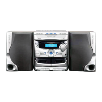
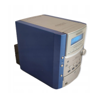
| Model | RXD-755L |
| Category | Stereo System |
| Language | English |
Detailed explanation of microprocessor port functions and I/O.
Description of IC pin functions for various integrated circuits.
Details on the RDS LSI and procedures for setting up test modes.
Breakdown of CD test mode operations, software reset, and initialization.
Guide for CD changer aging test and specification of system error messages.
Procedures for adjusting AM and FM tuner circuits.
Specific settings for AM intermediate frequency and radio frequency.
Details on automatic and manual adjustments for the CD player.
List and explanation of error codes encountered during CD operation.
Component layout diagram for the CD section printed circuit board.
Component layout diagrams for the main and power supply printed circuit boards.
Component layout diagram for the display section printed circuit board.