Do you have a question about the Kenwood RXD-251 and is the answer not in the manual?
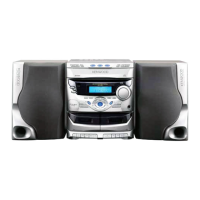
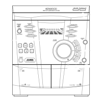
Diagram illustrating front panel controls and components.
Critical warning regarding laser radiation exposure when the unit is open.
Lists and illustrates accessories like antennas, remote control, and batteries.
Steps to reset the microcomputer to restore normal operation.
Diagram showing external connection terminals on the rear panel.
Details the functions of the remote control unit buttons.
Explains the buttons and knobs on the main component unit.
Describes buttons for cassette playback, recording, and tape handling.
Explains the various indicators and readouts on the unit's display.
Illustrates the interconnections between major internal units like Tuner, CD, and Audio.
Details the pin assignments and functions of the main microprocessor (IC601).
Describes microprocessor output signals, modes, and interface signals.
Explains the mechanical process for disc insertion and playback initiation.
Describes the operation of the disc tray open/close mechanism.
Step-by-step guide for replacing the CD pickup assembly.
Details the alignment steps for the FM tuner section.
Outlines the alignment steps for the SW tuner section.
Illustrates how to connect measurement instruments for alignment.
Procedure for demagnetizing and cleaning the tape heads and capstan.
Steps for adjusting head azimuth, tape speed, and playback levels.
Procedure for adjusting the laser diode power output.
Steps for adjusting the focus error bias for optimal disc reading.
Shows the wiring connections for the tuner and CD mechanism units.
Illustrates wiring for audio, display, and power supply sections.
Explains how to interpret capacitor part numbers and codes.
Details resistor coding for type, value, tolerance, and wattage.
Component placement diagram for the Tuner Unit variant.
Component placement diagram for another Tuner Unit variant.
Component placement diagram for the RXD-371S Tuner Unit.
Component placement diagram for the Audio Unit.
Component placement diagram for the Display Unit.
Detailed circuit diagram for specific Tuner Unit configurations.
Continuation of the Tuner Unit circuit diagram for other variants.
Circuit diagrams for the CD mechanism, switch boards, and motor unit.
Circuit diagrams for power supply, CD control, and sensor units.
Circuit diagrams for the cassette deck, sensor PCB, and display unit.
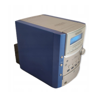
Visual representation of the main unit's components and their assembly.
Lists part numbers for chassis components, panels, and holders.
Lists part numbers for cassette deck buttons and control knobs.
Lists part numbers for control knobs and various capacitor types.
Lists part numbers for capacitors, coils, and transistors used in the unit.
Lists part numbers for integrated circuits and transistors.
Lists part numbers for additional capacitors and transistors.
Lists part numbers for integrated circuits, fuses, and switches.
Lists part numbers for diodes, ICs, and transistors.
Lists part numbers for LEDs, speakers, and other miscellaneous components.
Explains how to interpret the parts list format and abbreviations.
Provides technical details for the amplifier and cassette deck sections.
Lists specifications for the CD player, power consumption, dimensions, and weight.
Details the specifications for the included speaker systems.
Lists international contact information for Kenwood service and sales.
| Type | Stereo System |
|---|---|
| Output Power | 40W per channel |
| CD Player | Yes |
| Tuner | FM/AM |
| Tape Deck | Yes |
| Remote Control | Yes |
| Frequency Response | 20Hz - 20kHz |
| Functions | CD, Tuner, Tape Deck |