Do you have a question about the Kenwood RXD-551 and is the answer not in the manual?
Detailed steps on how to detach the front panel and CD mechanism units from the main unit.
Guidance on manually opening the CD tray when it fails to eject properly.
Schematic representation of the main functional blocks and their interconnections within the system.
Schematic illustrating the wiring connections between different units and components of the system.
Procedures for system initialization, microprocessor functions, and pin descriptions.
Details on tuner destination lists and operating the system in various test modes.
Step-by-step guides for adjusting the tuner, CD player, and cassette deck sections.
Component layouts for the CD and Cassette Mechanism Unit PC boards.
Schematic diagram for the Tuner Unit, illustrating FM and AM front-end circuits.
Schematics for the Audio Unit and Power Supply Unit, detailing their circuits.
Illustrated exploded views of the CD mechanism, cassette mechanism, and main unit for parts identification.
Instructions on interpreting the parts list, including model abbreviations and destination codes.
Detailed specifications for the amplifier, tuner, and cassette deck sections.
Specifications for the CD player, power consumption, dimensions, and weight.
| Brand | Kenwood |
|---|---|
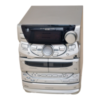
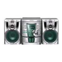
| Model | RXD-551 |
| Category | Stereo System |
| Language | English |