EasyManua.ls Logo

Kenwood RXD-552 User Manual

Kenwood RXD-552
47 pages
To Next Page IconTo Next Page
Page #1 background imageLoading...
Page #1 background image
Panel (CD)
(A29-1046-02)
Knob
(K29-7544-04)
Knob
(K29-7543-04)
Front glass
(B10-)
Front glass
(B10-3449-02)
Front glass
(B10-3471-03)
Knob
(K29-7541-02)
Knob
(K29-7541-02)
Knob
(K29-7545-04)
Panel *
(A60-)
Front glass
(B10-3448-02)
Cassette lid (R)
(A53-2122-02)
Cassette lid (L)
(A53-2121-02)
Phone jack
(E11-0280-05)
Knob
(K29-7553-01)
MINI HiFi COMPONENT SYSTEM
RXD-402/402E/402W/452/452E/452W/502/502E/
RXD-502W/552/552E/552W/572S/A41/A51
(XD-402~A51) **
SERVICE MANUAL
© 1999-1/B51-5500-00 (K/K) 3590
Illustration is RXD-402.
* Refer to parts list on page 48~.
In compliance with Federal Regulations, following are reproduc-
tions of labels on, or inside the product relating to laser product
safety.
**Refer to page 2 if you want to know system configuration.
KENWOOD-Crop. certifies this equipment conforms to DHHS
Regulations No. 21 DFR 1040. 10, Chapter 1, Subchapter J.
DANGER : Laser radiation when open and interlock defeated.
AVOID DIRECT EXPOSURE TO BEAM
RXD-402(E) INT1P 99.6.9 7:25 PM y[W 2
w
w
w
.
x
i
a
o
y
u
1
6
3
.
c
o
m
Q
Q
3
7
6
3
1
5
1
5
0
9
9
2
8
9
4
2
9
8
T
E
L
1
3
9
4
2
2
9
6
5
1
3
9
9
2
8
9
4
2
9
8
0
5
1
5
1
3
6
7
3
Q
Q
TEL 13942296513 QQ 376315150 892498299
Question and Answer IconNeed help?

Do you have a question about the Kenwood RXD-552 and is the answer not in the manual?

Kenwood RXD-552 Specifications

General IconGeneral
BrandKenwood
ModelRXD-552
CategoryStereo System
LanguageEnglish

Summary

External View and Disassembly for Repair

External View

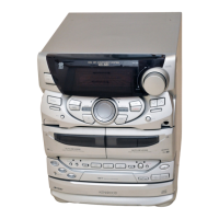
Shows the external components and layout of the main unit.

Disassembly for Repair

Provides instructions on how to open the tray if it does not come out.

Block Diagram

Circuit Description

1. Initialization

Details the initial setting and operation procedures for the microcomputer.

2. Destination list of TUNER

Lists tuner destination types with their corresponding frequency ranges and IF/RF settings.

3. Test mode operations

Explains test modes for receiver, cassette deck, and CD player, including operations.

4. Main microprocessor and interfaces

Overview of the microprocessor, block diagram, key matrix, and pin descriptions.

5. IC controller details

Lists the pins and functions for IC controllers like RDS LED driver.

Adjustment Procedures

Amp Adjustment

Procedure for adjusting the idle current of the amplifier section.

Tuner Adjustment

Steps for adjusting VCO, resonance point, and separation in the tuner section.

CD Player Adjustment

Instructions for setting laser power and focus error bias for CD player.

Cassette Deck Adjustment

Procedures for demagnetization, azimuth, playback level, and bias current.

Wiring Diagram

Exploded View (CD Mechanism)

Exploded View (Cassette Mechanism)

Exploded View (Unit)

Parts List

How to Read the Parts List

Abbreviation of Model and Mass Production's Destinations

Explains abbreviations for countries and models used in the parts list.

Specifications

Main unit specifications

Details amplifier, tuner, and cassette deck specs for the main unit.

CD player and General specifications

Covers CD player laser, wow & flutter, power, dimensions, and weight.

Related product manuals