EasyManua.ls Logo

Kenwood RXD-571S User Manual

Kenwood RXD-571S
76 pages
To Next Page IconTo Next Page
Page #1 background imageLoading...
Page #1 background image
RYO-SOVBEBOIWESIStESsINlTisie!|
SENWOOD
TOA/TOAE/7O1W/751/751E/751W/771S/A8
SERVICE
MANUAL
(XD-501
~A8)**
,
©
1998-3/B51-5420-00
(K/K)
3661
Front
glass*
Lighting
board
Lighting
board
Panel
assy*
(B10-)
(B19-1589-04) (B19-1586-04)
(A60-)
|
MINI
HiFi
COMPONENT
SYSTEM
SRS
(@)
VOLUME
CONTROL,
Knob*
(K29-)
PHONES
aie
Phone
jack
Phone
jack
(E11-0280-05)
(E11-0169-05)
Cassette
lid
(L)*
—-—-—_,7—*
o—_._______-—_
Cassette
lid
(R)*
(A53-)
(A53-)
Front
glass
open
eee
Front
glass
(B10-2446-13)
(B10-2447-13)
pinac?
SnoGnAM
SEARCH
SYSTEM
pmact
penanan
BEANGH
SvaTEM
Aww
oii
Lighting
board
GaN
as
aro
a
Co)
e"o”
(B19-1587-03)
eastern
©
(_o_]e00)
Panel
(CD)*
KENWOOD
.
(A29-)
**Refer
to
page
2
if
you
want
to
know
system
configuration.
*
Refer
to
parts
list
on
page
58.
-KENWOOD-Crop.
cettifies
this
equipment
conforms
to
DHHS
In
compliance
with
Federal
Regulations,
following
are
reproduc-
Reguniiong
No.
21
DFR
1040.
10,
Chapter
1,
Subchapter
J.
tions
of
labels
on,
or
inside
the
product
relating
to
laser
product
safety.
Refer
to
RXD-500/700
(B51-5300-00),
If
you
require.
TUNER
preset
frequency
in
detail.
S
DANGER:
Laser
radiation
when
open
and
interlock
defeated.
AVOID
DIRECT
EXPOSURE
TO
BEAM
Question and Answer IconNeed help?

Do you have a question about the Kenwood RXD-571S and is the answer not in the manual?

Kenwood RXD-571S Specifications

General IconGeneral
BrandKenwood
ModelRXD-571S
CategoryStereo System
LanguageEnglish

Summary

External View

Disassembly for Repair

Block Diagram

Circuit Description

Main Microprocessor

Overview of the main microprocessor and its peripheral connections.

Pin Description

Detailed description of the microprocessor's pin functions and their purposes.

Adjustment Procedures

CD Player Test Mode

Procedures for setting and canceling the CD player's test mode.

Deck Section Test Mode

Procedures for setting and canceling the deck section's test mode.

Cassette Deck Adjustment

Detailed steps for adjusting the cassette deck's mechanisms and boards.
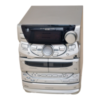
Wiring Diagram

CD Mechanism PC Board

MPX Unit PC Board

Tuner Unit PC Board

Audio Unit PC Board

Display Unit PC Board

Exploded View: CD Mechanism

Exploded View: Cassette Mechanism

Parts List

System Specifications

Related product manuals