Do you have a question about the Kenwood RXD-550 and is the answer not in the manual?
Instructions for removing the main printed circuit board for repair purposes.
Step-by-step procedures and alignment points for adjusting the tuner.
Procedures for adjusting laser power, tracking, focus, and gain for the CD player.
Detailed procedures for demagnetization, cleaning, and PC board adjustments for the cassette deck.
| Brand | Kenwood |
|---|---|
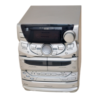
| Model | RXD-550 |
| Category | Stereo System |
| Language | English |