EasyManua.ls Logo

Kenwood RXD-755 User Manual

Kenwood RXD-755
34 pages
To Next Page IconTo Next Page
Page #1 background imageLoading...
Page #1 background image
70%
MINI HiFi COMPONENT SYSTEM
RXD-655/655-GR/655-H/655E/655E-GR
© 2001-6 PRINTED IN KOREA
B51-5737-00 (K/K) 2308
Panel ass'y *
(A60-)
Knob(VOLUME)
(K27-2470-08)
Dress ring
(A21-3957-08)
In compliance with Federal Regulations, following are repro-
duction of labels on, or inside the product relating to laser prod-
uct safety.
KENWOOD-Crop. certifies this equipment conforms to DHHS
Regulations No.21 CFR 1040. 10, Chapter 1, subchapter J.
DANGER : Laser radiation when open and interlock defeated.
AVOID DIRECT EXPOSURE TO BEAM.
* Refer to parts list on page 33.
Panel(CD)
(A60-2090-08)
Front glass *
(B10-)
RXD-655E-H/655L/655M/655M-H
RXD-755/755E/755L/755M
SERVICE MANUAL
(XD-655~855)**
**Refer to page 2 if you want to know system configuration.
Question and Answer IconNeed help?

Do you have a question about the Kenwood RXD-755 and is the answer not in the manual?

Kenwood RXD-755 Specifications

General IconGeneral
BrandKenwood
ModelRXD-755
CategoryStereo System
LanguageEnglish

Summary

MINI HiFi Component System Service Manual

Front Panel Controls Overview

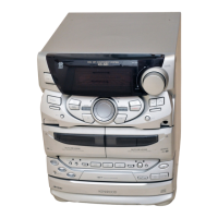
Identifies main controls and displays on the front panel.

System Configuration and Safety

System Configuration and Safety Cautions

Lists system configurations, accessories, and important safety warnings.

External View and Connections

Input/Output Terminal Identification

Details the various connection ports for external devices and antennas.

Disassembly for Repair

Disassembly Procedures and Notes

Provides step-by-step instructions and crucial precautions for unit disassembly.

Tape and CD Mechanism Disassembly Details

Specific instructions for removing tape and CD mechanism components.

System Block Diagram

Circuit Description

Microprocessor Ports and IC Functions

Details microprocessor ports, IC pin functions, and test mode operations.

Test Mode, Initialization, and Errors

Instructions for test modes, CD changer initialization, and error handling.

Adjustment Procedures

Tuner and CD Section Adjustments

Covers manual and automatic adjustment procedures for the tuner and CD sections.

PC Board Layout Diagrams

CD Section PC Board Layout

Shows component placement on the CD section printed circuit board.

Main Section PC Board Layout

Shows component placement on the main section printed circuit board.

Power Section PC Board Layout

Shows component placement on the power supply section printed circuit board.

Display Section PC Board Layout

Shows component placement on the display control section printed circuit board.

Exploded Views

CD Mechanism Exploded View

Illustrates the assembly of the CD mechanism with numbered parts.

Unit Exploded View

Shows the overall unit assembly with numbered external and internal parts.

Parts List

Component Part Numbers and Descriptions

Lists all replaceable parts with their numbers, descriptions, and applicable models/destinations.

System Specifications

Related product manuals