EasyManua.ls Logo

Kenwood RXD-M31MD User Manual

Kenwood RXD-M31MD
42 pages
To Next Page IconTo Next Page
Page #1 background imageLoading...
Page #1 background image
70%
678 679
620
605
680
681
677
686
674
684
607
612
683
682
685
676
675
603
614
JK602
(HM-381MD)
MICRO HiFi COMPONENT SYSTEM
RXD-M31MD/
LS-M31
(
M
)
SERVICE MANUAL
© 1999-12/B51-5555-00 (K/K) 1853
KENWOOD-Crop. certifies this equipment conforms to DHHS
Regulations No. 21 DFR 1040. 10, Chapter 1, Subchapter J.
DANGER : Laser radiation when open and interlock
defeated.
AVOID DIRECT EXPOSURE TO BEAM
* Refer to parts list on page 42.
In compliance with Federal Regulations, following are repro-
ductions of labels on, or inside the product relating to laser
product safety.
Front cabinet
(A60-1745-08)
Top panel
(A21-3801-08)
Knob (MD EJECT)
(K29-7702-08)
Knob (VOLUME)
(K29-7690-08)
Control panel *
(A21-)
Knob (ON/STANDBY)
(K29-7700-08)
Cass door cover
(A02-2945-08)
Headphone jack
(E11-0398-08)
MD door
(A52-0376-08)
Knob (TAPE/STOP)
(K29-7699-08)
Knob (MD/CD PLAY)
(K29-7698-08)
Knob (PANEL BUTTON)
(K29-7701-08)
Knob (MENU)
(K29-7692-08)
Knob (TAPE REC)
(K29-7691-08)
Knob
(SET DEMO)
(K29-7694-08)
Knob (REPEAT)
(K29-7693-08)
Display lens
(B12-0386-08)
Cass door lens
(B10-3524-08)
Tuning panel
(A21-3779-08)
Knob (MD REC)
(K29-7696-08)
Knob (SOUND)
(K29-7697-08)
Knob (FF/TUNER/AUX)
(K29-7695-08)
Question and Answer IconNeed help?

Do you have a question about the Kenwood RXD-M31MD and is the answer not in the manual?

Kenwood RXD-M31MD Specifications

General IconGeneral
BrandKenwood
ModelRXD-M31MD
CategoryStereo System
LanguageEnglish

Summary

Micro HiFi Component System Service Manual

External View and Component Identification

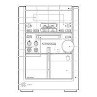
Diagram illustrating front panel controls, indicators, and external connections.

Manual Contents, Accessories, and Cautions

System Accessories

Lists and illustrates various accessories provided with the component system.

Microcomputer Reset Procedure

Instructions for resetting the microcomputer to restore normal operation.

External View of Rear and Side Panels

Rear Panel Connections and Ports

Details on antenna inputs, digital outputs, and analog inputs/outputs.

System Block Diagram

Component Interconnections Overview

Diagram showing the functional blocks and signal flow within the unit.

Circuit Description and Initialization

System Initialization Procedures

Steps for setting initial conditions and performing initialization operations.

Tuner Preset Frequency Configuration

List of preset frequencies for tuner channels based on destination.

Microprocessor Pin Descriptions

Main Microprocessor Pin Details

Detailed description of each pin's function for the main microprocessor.

MD Section Circuit Description

MD Microprocessor Pin Details

Detailed description of each pin's function for the MD microprocessor.

Test Mode Entry and Operation

Instructions for entering and operating the receiver's test mode.

Test Mode Operations for CD and MD

CD Player Test Mode Procedures

Details on setting and operating the CD player in test mode.

MD Player Test Mode Operations

Procedures for various test modes of the MD player, including adjustment.

MD Player Test Mode Details

Optical Pickup Grating Inspection Method

Procedure for inspecting and adjusting the optical pickup grating.

Jitter Adjustment and Checking Method

Method for adjusting and checking jitter in MD player operation.

CD Player Test Mode Operations

CD Player Test Mode Indicators and Errors

Explanation of display indicators and error messages in CD player test mode.

MD Mechanism Error Message Reference

Table detailing error messages for the MD mechanism and their meanings.

Tuner and CD Player Adjustments

Cassette Deck Adjustment Procedures

Instructions for adjusting the cassette deck's heads and bias.

Waveform Examples: PLAY Mode

Waveforms: Groove and Pit Play Modes

Oscilloscope waveforms for CD player groove and pit play.

Waveforms: Power Off/Standby States

Oscilloscope waveforms showing power supply states.

Waveform Examples: D/A Conv. and Digital Rec

Waveforms: Analog Record and Sine Wave Play

Oscilloscope waveforms for A/D conversion and sine wave playback.

MD Main PWB-A Component View

MD Pickup Unit Connection Point

Diagram showing the connection of the MD pickup unit to the PWB.

MD Main PWB-A Bottom View

MD Mechanism Motors and Switches

Identification of MD mechanism motors and switch locations on PWB.

Control Unit PCB Layout

Display Unit PCB Layout

Component layout for the display unit's printed circuit board.

Cassette Deck Unit PCB Layout

Power Unit PCB Layout

Component layout for the power unit's printed circuit board.

Headphone and Speaker Board Layouts

Transformer Board Component Layout

Component layout for the transformer board.

Main Unit PCB Layout

Tuner Input and Control Components

Component layout for tuner input and control sections on main unit.

MD Mechanism Switch PWB Layout

MD Mechanism Control Signal Details

Diagram and voltage measurements for MD mechanism control.

MD Control and Power Circuit Schematics

MD Mechanism Control IC Details

Schematic details for MD mechanism control ICs.

Main Board Schematic: CD and Tuner Sections

CD Mechanism Control and RF Amplifier Schematic

Schematic for CD mechanism control and RF amplifier circuits.

Main Board Schematic: Tuner and Control ICs

Tuner and Volume Control IC Schematics

Schematic details for tuner and volume control ICs.

Main Board Schematic: Power and Control

Power Supply and Control Circuit Schematic

Schematic for power supply and control circuits on the main board.

Cassette Board Schematic

MD Control Board Schematic Details

Schematic diagram for the MD control board.

Power Board Schematic

Transformer Board Schematic Details

Schematic diagram for the transformer board.

MD Mechanism Exploded View

MD Mechanism Part Identification Guide

Diagram showing assembly and part numbers for the MD mechanism.

Cassette Deck Mechanism Exploded View

Cassette Deck Mechanism Part Identification

Diagram showing assembly and part numbers for the cassette deck.

Exploded View of System Units

Front Panel Unit Part Identification

Diagram showing assembly and part numbers for the front panel unit.

Parts List: Electrical Components (C)

Parts List: Screws, Transformers, and Connectors

List of screws, transformers, and connectors with part numbers.

Parts List: Capacitors (C310-C804A)

Parts List: Capacitors (C805-C1304)

List of capacitors with part numbers and specifications.

Parts List: Connectors and Fuses

Parts List: Resistors (R102A-R156A)

List of resistors with part numbers and values.

Parts List: Resistors (R201A-R569A)

Parts List: Resistors (R601A-R949A)

List of resistors with part numbers and values.

Parts List: Resistors (R605A-R879A)

Parts List: Resistors (R880A-R1036A)

List of resistors with part numbers and values.

Parts List: Resistors (R1018A-R1036A)

Parts List: Switches, Diodes, and Integrated Circuits

List of switches, diodes, and ICs with part numbers.

Parts List: Diodes, ICs, and Transistors

Parts List: Transistors and MD Mechanism Components

List of transistors and MD mechanism parts with part numbers.

Parts List: MD Mechanism Components (C1400-C1805)

Parts List: MD Mechanism Components (R1100-R1536)

List of MD mechanism components (resistors) with part numbers.

Parts List: MD Mechanism Components (R1412-R1536)

Parts List: MD Mechanism Switches, Diodes, ICs, Transistors

List of MD mechanism switches, diodes, ICs, and transistors.

Parts List: Cassette Mechanism and Speaker Parts

Parts List: Cassette Mechanism Motors and Pickups

List of cassette mechanism motors, pickups, and related parts.

System Specifications

Amplifier and Tuner Section Specifications

Technical specifications for the amplifier and tuner sections.

Cassette Deck and General Specifications

Specifications for the cassette deck and overall unit.

Manufacturer Contact Information

Kenwood Regional Service and Sales Offices

List of Kenwood service and sales offices worldwide.

Related product manuals