EasyManua.ls Logo

Kenwood RXD-V525 User Manual

Kenwood RXD-V525
50 pages
To Next Page IconTo Next Page
Page #1 background imageLoading...
Page #1 background image
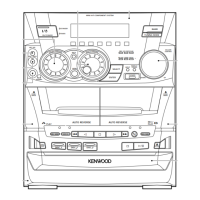
MINI HiFi COMPONENT SYSTEM
RXD-V525/V626/V727/V828
SERVICE MANUAL
(XD-V525~V828) **
© 1999-8/B51-5567-00 (K/K) 406
70%
In compliance with Federal Regulations, following are repro-
ductions of labels on, or inside the product relating to laser
product safety.
**Refer to page 2 if you want to know system configuration.
Refer to the RXD-652 service manual (B51-5517-00) for
DISASSEMBLY FOR REPAIR.
KENWOOD-Crop. certifies this equipment conforms to DHHS
Regulations No. 21 DFR 1040. 10, Chapter 1, Subchapter J.
DANGER : Laser radiation when open and interlock
defeated.
AVOID DIRECT EXPOSURE TO BEAM
PHONES
AUTO REVERSE
DIRECT PROGRAM SEARCH SYSTEM
A
PLAY
B
REC/
PLAY
AUTO REVERSE
DIRECT PROGRAM SEARCH SYSTEM
MENU
DISC
SKIP
0
PUSH
OPEN
MINI HI-FI COMPONENT SYSTEM
XD-552
PBC
KEY CONT
ECHO
EX.BASS
SELECT
ENTER
INPUT
DISPLAY
/DEMO
MIC VOL
MIN. MAX.
MIC
BACK
BAND
TUNING MODE
1
@&
¡
#
REV. MODE REC/ARMTAPE EQ.
0
PUSH
OPEN
A
B
DISC
3
DISC
0
OPEN
VIRTUAL
&
^
1
DISC
2
R D S
ON/STANDBY
S
O
U
N
D
C
O
N
T
R
O
L
M
U
L
T
I
C
O
N
T
R
O
L
DOWN
DOWN UP
VOLUME
CONTROL
UP
STANDBY
TIMER
PRO LOGIC
3 STEREO
MIC VOL.
Knob
(K29-7470-14)
Front glass *
(B10-)
Knob
(K29-7471-14)
Knob
(K29-7547-04)
Phone jack
(E11-0219-05)
Phone jack
(E11-0280-05)
Cassette lid assy(L) *
(A53-)
Panel assy *
(A60-)
Knob
(K29-7466-04)
Cassette lid assy(R) *
(A53-)
Panel assy(CD)
(A29-1067-03)
* Refer to parts list on page 55.
Question and Answer IconNeed help?

Do you have a question about the Kenwood RXD-V525 and is the answer not in the manual?

Kenwood RXD-V525 Specifications

General IconGeneral
Number of Channels5.1
Frequency Response20 Hz - 20 kHz
TypeStereo Receiver
Remote ControlYes
SpeakersNot included
Tuner TypeDigital
Preset Stations40
Input Sensitivity200mV
FunctionsCD, Tape
Tuner BandsAM, FM
Input Sensitivity/Impedance47 kOhm

Summary

External View

Block Diagram

Circuit Description

Test Modes

Covers diagnostic modes for CD, Deck, Sub Clock, and Initialize functions.

Main Microprocessor and IC Descriptions

Details the main microprocessor, its peripherals, expander ICs, and pin functions.

Microprocessor Pin Descriptions

Lists and describes pins for the main microprocessor.

Expander IC Pin Descriptions

Details pin functions for expander ICs.

Adjustment

CD Player Adjustment

Procedures for adjusting CD player laser power, focus, and bias.

Cassette Deck Adjustment

Steps for demagnetization, cleaning, and head/PC board adjustments.

PC Board Adjustment

Covers adjustments for tape speed, playback level, and bias current on PC boards.

Wiring Diagram

PC Board Layouts

Power Supply Unit

Component layout diagram for the power supply section.

Power Amplifier Unit

Component layout diagram for the power amplifier section.

Record/Playback Unit

Component layout diagram for the record/playback mechanism.

Sub-Circuit Unit

Component layout diagram for the sub-circuit board.

Display Unit

Component layout diagram for the display unit.

CD Player Unit

Component layout diagram for the CD player mechanism.

Related product manuals