EasyManua.ls Logo

Kenwood RXD-V313 User Manual

Kenwood RXD-V313
25 pages
To Next Page IconTo Next Page
Page #1 background imageLoading...
Page #1 background image
MINI HiFi COMPONENT SYSTEM
RXD-V313
SERVICE MANUAL
© 1998-8/B51-5463-00 (K/K) 376
(XD-V313)
In compliance with Federal Regulations, following are reproduc-
tions of labels on, or inside the product relating to laser product
safety.
KENWOOD-Crop. certifies this equipment conforms to DHHS
Regulations No. 21 DFR 1040. 10, Chapter 1, Subchapter J.
DANGER : Laser radiation when open and interlock defeated.
AVOID DIRECT EXPOSURE TO BEAM
Refer to RXD-251/301/301E/301W/351/351E/351W/371S/A3
service manual(B51-5454-00), if you require mechanism
operation description in detail.
Please replace with the new pcb and/or mechanism on CD
player if it doesn't work.
DISC 1 DISC 2 DISC 3
0
76
¢4
ROCK
FLAT
EX.BASS
POP
JAZZ
A B
3
7/08 3 1¡7/08
MC1
MC2
MIN
MIN
MAX
MAX
MIC VOLUME
ECHO LEVEL
STANDBY
VIDEO CD HIT MASTER
INPUT
ON/STANDBY
TIMER SET
CLOCK
DISPLAY
/DEMO
AUTO/MONOTIMER
BAND
TUNING
PHONES
UP
DOWN
AUTO
PRESET
MANUAL
PRESET
RECORDING/ PLAYBACK
PLAY BACK
DISC
SKIP
Panel(CD)
(A60-1579-08)
Front glass
(A29-1048-08)
Knob
(K29-7535-08)
Knob
(K29-7534-08)
Knob
(K29-7519-08)
Knob
(K29-7518-00)
Jack(H/P)
(E11-0386-08)
Knob
(K29-7516-08)
Cassette lid(R)
(A53-2104-08)
Front glass(L)
(B10-3451-08)
Front panel
(A60-1575-08)
Knob
(K29-7533-08)
Knob
(K29-7512-08)
Indicator led lens
(B19-1602-08)
Knob
(K29-7521-08)
Knob
(K29-7522-08)
Knob
(K29-7523-08)
Cassette lid(L)
(A53-2103-08)
Front glass(L)
(B10-3450-08)
Knob
(K29-7515-08)
Knob
(K29-7511-08)
Jack(MIC)
(E11-0387-08)
Knob
(K29-7549-08)
Knob
(K29-7513-08)
RXD-V313(K) COVER1,1( 98.12.11 9:46 y[W 2
Question and Answer IconNeed help?

Do you have a question about the Kenwood RXD-V313 and is the answer not in the manual?

Kenwood RXD-V313 Specifications

Amplifier Section IconAmplifier Section
effective output power during STEREO operation60 W + 60 W
input sensitivity / impedance AUX300 mV / 40 kΩ
input sensitivity / impedance MIC 1, 22.5 mV / 2.2 kΩ
Tuner Section IconTuner Section
FM tuning frequency range87.5 MHz ~ 108 MHz
AM tuning frequency range (9 kHz step)531 kHz ~ 1, 602 kHz
AM tuning frequency range (10 kHz step)530 kHz ~ 1, 610 kHz
Cassette Deck Section IconCassette Deck Section
track4-track, 2-channel stereo
recording systemAC bias system (Frequency: 105 kHz)
fast winding timeApprox. 100 seconds (C-60 tape)
Video CD Player Section IconVideo CD Player Section
laserSemiconductor laser
video output formatNTSC/PAL
composite video output level1 Vp-p (75 Ω, negative sync)
General IconGeneral
power consumption180 W
dimensionsW: 280 mm (11”) H: 320 mm (12-5/8”) D: 405 mm (15-15/16”)

Summary

External View

Block Diagram

Circuit Description

Microprocessor Pin Descriptions

Details pins for IC601 and MPEG microprocessor IC03.

Key Matrix and LCD Light Mode

Explains button input mapping and special LCD display function.

Adjustment Procedures

FM/MW Tuning and Tracking Adjustments

Covers IF, tracking, and VT calibration for FM and MW tuner sections.

Cassette Deck Calibration and PC Board Settings

Details head azimuth, tape speed, and playback level adjustments.

Wiring Diagram

PC Board Component Layouts

Audio, AC SW, AC Cord, Headphone, Record Switch Units

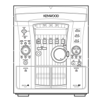
Component layout diagrams for specific system units.

CD Control, Display, Sensor, MIC Mix, Video O/P Units

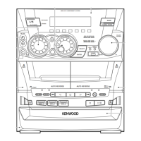
Component layout diagrams for other system units.

Unit System Diagrams

Tuner, CD Mecha, MPEG, Audio, and Mic Mix Units

Diagrams showing internal connections for key functional units.

Exploded View (Unit Assembly)

Parts List

Specifications

Related product manuals