EasyManua.ls Logo

Kenwood RXD-V535S User Manual

Kenwood RXD-V535S
43 pages
To Next Page IconTo Next Page
Page #1 background imageLoading...
Page #1 background image
70%
MINI HiFi COMPONENT SYSTEM
© 2000-8/B51-5654-00 (K/K) 707
DISC
DISC
DISC
STANDBY
TIMER
DISPLAY/DEMO
MENU
SELECTBACK ENTER
SOUND
CONTROL
TUNING
MODE
M
U
L
T
I
C
O
N
T
R
O
L
REC/ARM
REVERSE
MODE
TAPE EQ.
PHONES
DISC SKIP
OPEN/
CLOSE
E
X
.
B
A
S
S
PUSH
OPEN
PUSH
OPEN
VOLUME
CONTROL
MIC
MIC
VOL.
MIN MAX
SVCD
PBC
VCD
RXD-V333/V333S/V535/V535-GR/V535S/
RXD-V535S-H/V636/V737/V737S
SERVICE MANUAL
(XD-V333~V737)**
In compliance with Federal Regulations, following are repro-
duction of labels on, or inside the porduct relating to laser prod-
uct safety.
KENWOOD-Crop. certifies this equipment conforms to DHHS
Regulations No.21 CFR 1040. 10, Chapter 1, subchapter J.
DANGER : Laser radiation when open and interlock defeated.
AVOID DIRECT EXPOSURE TO BEAM.
**Refer to page 2 if you want to know system configuration.
Panel ass'y
(A60-1898-01)
Knob
(K29-7721-04)
Panel(CD)
(A29-1119-02)
Front glass
(B10-3629-02)
Knob
(K29-7722-04)
Phone jack
(E11-0280-05)
Phone jack
(E11-0219-05)
Illustration is RXD-V737(M).
Question and Answer IconNeed help?

Do you have a question about the Kenwood RXD-V535S and is the answer not in the manual?
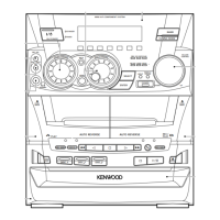
Kenwood RXD-V535S Specifications

General IconGeneral
Tuner BandsAM/FM
Tuner TypeDigital
Preset Stations40
CD PlayerYes
Remote ControlYes
Speaker Impedance6 ohms
Tape DeckDouble Cassette Deck

Summary

Contents and Accessories

Accessories

Lists all included accessories with their respective part numbers.

System Configuration Details

Details system models, main units, destinations, and speaker pairings.

Important Cautions and Operations

Provides guidance on resetting the microcomputer and other operational warnings.

External View of Unit Components

Disassembly for Repair Instructions

Circuit Description

Initialization and System Setup

Covers initial conditions, initializing operation, and system setup procedures.

Tuner Destination List and Test Mode

Details tuner settings and procedures for entering test mode.

Microprocessor and Key Matrix Functions

Adjustment Procedures

CD Player Adjustment Steps

Guides on adjusting laser current and FB bias for the CD player.

Cassette Deck Adjustment

Measurement Equipment Connections

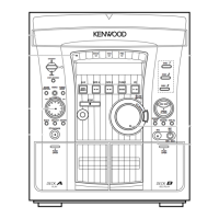
Diagrams showing how to connect measurement equipment for adjustments.

Wiring Diagram

PC Board Component Layouts

Exploded View of CD Mechanism

Exploded View of Main Unit

Parts List Overview

Parts Description Guide

System Specifications

Related product manuals