Do you have a question about the Kenwood TM-401A and is the answer not in the manual?
Lists available microphones and the external communications speaker.
Details the speaker mounting kits and associated hardware for installation.
Includes the DC power cord, spare fuse, and the instruction manual.
Highlights the transceiver's compact size and advanced microcomputer processing capabilities.
Describes the functions for managing multiple frequencies and recalling stored memory channels.
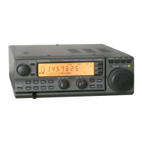
Focuses on the unit's construction quality and its transmission/reception audio performance.
Explains the HI/LOW power switch and features related to repeater communication.
Explains the VFO tuning control and the squelch adjustment for noise elimination.
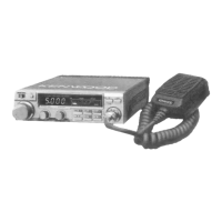
Describes the combined control for turning the unit ON/OFF and adjusting volume.
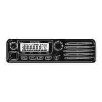
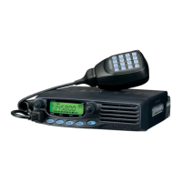
Introduces the front panel keyboard layout and its primary functions.
Details the keys for accessing memory channels and initiating scan operations.
Explains the specific functions of the MHz, ALERT, and A/B selection keys.
Describes the 8-pin microphone connector and the COM channel key.
Covers the operation of tone switches for British and European versions.
Explains the function of the switch that controls transmitter output power.
Details the frequency display, scan indicator, and various status LEDs.
Describes controls for repeater shift monitoring and transmit frequency offset.
Details the antenna, DC power, and external speaker connectors on the rear panel.
Explains the jack for connecting the optional remote frequency control unit.
Describes the controls and functions specific to the USA version microphone.
Details the controls and functions for microphones used in versions other than USA.
Covers antenna selection for UHF mobile operation and mobile unit placement guidelines.
Provides instructions and examples for mounting the communications speaker.
Details the steps for securing speaker mounting brackets and the transceiver unit.
Guides on connecting the antenna system and ensuring a stable DC power supply.
Offers tips for reducing radio interference caused by vehicle ignition systems.
Specifies the required DC power supply and antenna types for fixed station use.
Explains how to receive signals, use the squelch control, and tune frequencies.
Guides on transmitting, power output levels, and important operational precautions.
Details the 16-key auto patch operation and verification beep tone functions.
Step-by-step instructions for storing frequencies in memory channels.
Explains how to initiate and control memory scan operations.
Details setting programmable scan ranges and controlling scan direction.
Instructions on how to stop memory or programmable scan modes.
Explains the alert function for monitoring memory channel 1 when busy.
Procedures for removing unit covers and adjusting the beeper volume.
Information on the lithium battery's lifespan and the microprocessor reset procedure.
Describes the operation and connection of the optional FC-10 remote control unit.
Explains display elements, keyboard functions, and available power supply options.
Details the components of the TU-3 unit and its installation process.
Explains transmitter protection mechanisms and battery precautions.
Guides on ordering replacement parts and initiating service or repair.
Lists overall technical parameters including semiconductors, frequency range, and dimensions.
Details transmitter output power, modulation, frequency tolerance, and spurious radiation.
Outlines receiver circuitry, intermediate frequencies, sensitivity, and selectivity.
Provides technical details for the supplied auto patch microphone.
| Mode | FM |
|---|---|
| Voltage | 13.8 VDC |
| Power Supply | 13.8V DC |
| Intermediate Frequencies | 455 kHz |
| Receiver Sensitivity | 0.5 µV |
| Sensitivity | 0.5 µV |