Do you have a question about the Kenwood TR-7625 and is the answer not in the manual?
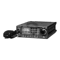
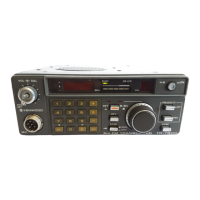
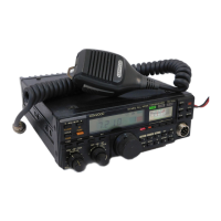
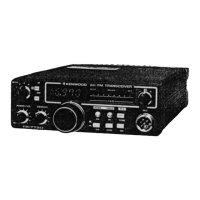
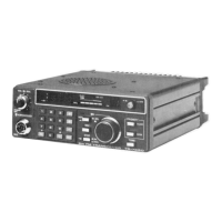
Overview of the KENWOOD TR-7625 2-meter transceiver for amateur radio.
General overview of the TR-7625 transceiver's features and capabilities.
Detailed explanation of the Phase Locked Loop circuit used for frequency synthesis.
Explanation of the PLL's phase-locked loop operation, including frequency division.
Description of ±5 kHz, Shift, Memory Shift circuits and Control Unit frequency settings.
Detailed description of the TR-7625's transmitter section circuitry.
Detailed description of the TR-7625's receiver section circuitry.
Safety guidelines for handling the SM5111A IC, including electrostatic discharge protection.
Explanation of the SM5111A LSI's internal structure and operating principles for PLL control.
Electrical specifications and maximum ratings for the 3SK74 dual-gate MOS FET.
Maximum ratings and electrical characteristics of the M57712H RF power module.
Identification and description of controls and indicators on the transceiver's front panel.
Identification of connectors and ports located on the transceiver's rear panel.
Visual guide to the internal components as viewed from the top of the unit.
Visual guide to the internal components as viewed from the bottom of the unit.
Detailed schematic diagram for the TX-RX unit (X44-1320-10).
Detailed schematic diagram for the Tone Unit (X52-1110-51).
Detailed schematic diagram for the PLL Unit (X50-1580-10).
Detailed schematic diagram for the Control Unit (X54-1440-10).
List of general capacitors, semiconductors, coils, potentiometers, and miscellaneous parts.
Comprehensive parts list for the TX-RX Unit (X44-1320-10), including capacitors.
Parts list for TX-RX unit semiconductors, potentiometers, trimmers, coils, and miscellaneous items.
Complete parts list for the PLL Unit (X50-1580-10), including capacitors, semiconductors, and coils.
Parts list for the Control Unit (X54-1440-10), including capacitors, resistors, semiconductors, and potentiometers.
Instructions and diagrams for packing the transceiver and its accessories.
Step-by-step instructions and diagrams for installing mounting brackets.
Exploded view of the unit and guide for removing panels and cases.
Diagnostic flowcharts and potential causes for PLL circuit issues.
Diagnostic flowcharts for transmitter output, power, and modulation problems.
Diagnostic flowcharts for receiver sensitivity, noise, and squelch issues.
List of essential test equipment needed for alignment and adjustments.
Step-by-step procedures for tuning and adjusting the PLL circuit parameters.
Further steps and settings for adjusting the PLL circuit for optimal performance.
Procedure for adjusting coils, including applying wax seal for stability.
Detailed procedures for adjusting transmitter parameters like RF power and BPF.
Adjustments for RF output, frequency check, and protection settings.
Procedures for setting frequency deviation and troubleshooting abnormal oscillations.
Adjusting frequency shift and memory functions for transmit and receive.
Further steps for adjusting frequency shift and memory functions.
Step-by-step procedures for aligning and adjusting the receiver section.
Procedures for adjusting signal-to-noise ratio and squelch threshold.
Identification and location of test points on the PLL Unit PC board.
Identification and location of test points on the TX-RX Unit PC board.
Diagrams showing test equipment connections for PLL and TX adjustments.
Diagrams illustrating test setups for various TX adjustments.
Diagrams illustrating test setups for various RX adjustments.
Diagram showing signal levels at various stages of the receiver section.
Diagram showing signal levels at various stages of the transmitter section.
A high-level block diagram illustrating the functional units of the transceiver.
The complete electronic schematic diagram for the TR-7625 transceiver.
Explanation of the logic and BCD codes for control unit switches.
Description and function of various terminals and connectors.
Guidelines for safely handling semiconductor devices to prevent static damage.
Overall specifications for the transceiver, including semiconductors, frequency range, and dimensions.
Detailed specifications for the transmitter section, including RF output power and modulation.
Detailed specifications for the receiver section, including sensitivity and selectivity.
| operating temperature | -20 to +50°C |
|---|---|
| power voltage | 11.5V DC to 16.0V DC |
| DC current | Less than 0.5A in receive, Less than 6A in HI transmit |
| RF output power | High: 25 watts, Low: 5 watts |
| max. frequency deviation | ±5 kHz |
| spurious radiation | Less than -60 dB |
| sensitivity | Less than 0.4 µV for 20 dB quieting |
| squelch sensitivity | Less than 0.25 µV |
| pass band width | Better than 12 kHz at 6 dB down |
| selectivity | Better than 76 dB at 30 kHz of adjacent channel |
| image rejection | Better than 70 dB |
| spurious interference | Better than 60 dB |
| intermodulation | Better than 66 dB |
| audio output | More than 1.5 watts across 8Ω load |
| dimensions | 161 mm wide, 61 mm high, 230 mm deep |
|---|---|
| weight | 1.75 kg |
| operating temperature | -20 to +50°C |
|---|---|
| power voltage | 11.5V DC to 16.0V DC |
| DC current | Less than 0.5A in receive, Less than 6A in HI transmit |
| RF output power | High: 25 watts, Low: 5 watts |
| max. frequency deviation | ±5 kHz |
| spurious radiation | Less than -60 dB |
| sensitivity | Less than 0.4 µV for 20 dB quieting |
| squelch sensitivity | Less than 0.25 µV |
| pass band width | Better than 12 kHz at 6 dB down |
| selectivity | Better than 70 dB at 25 kHz of adjacent channel |
| image rejection | Better than 70 dB |
| spurious interference | Better than 60 dB |
| intermodulation | Better than 60 dB |
| audio output | More than 1.5 watts across 8Ω load |
| dimensions | 161 mm wide, 61 mm high, 230 mm deep |
|---|---|
| weight | 1.75 kg |