Do you have a question about the Kenwood TR-7400A and is the answer not in the manual?
Detailed description of the Voltage Controlled Oscillator unit.
Detailed description of the Phase Detector unit.
Explanation of the programmable counter and TX-offset circuits.
Description of the tone squelch circuit operation.
Description of the Voltage Controlled Tuning circuit.
Description of the final output stage and related circuits.
PC board layout for the Power Amplifier unit.
PC board layout for the Phase Detector unit.
PC board layout for the Voltage Controlled Oscillator unit.
Instructions for removing the top and bottom case assemblies.
Instructions for removing the front panel assembly.
Instructions for removing the indicator section.
Instructions for removing the final transmitter section.
Instructions for removing the transmitter unit.
Instructions for removing the sub panel and LED mother board.
Diagnosis and remedies for PLL circuit issues.
Troubleshooting steps for transmitter performance problems.
Troubleshooting steps for receiver performance problems.
List of necessary test equipment for adjustments.
General overview of the TR-7400A adjustment procedures.
Detailed adjustment procedures for PLL, VCO, and TX units.
Adjustments for PA unit, RF meter, power, and control circuits.
| Brand | Kenwood |
|---|---|
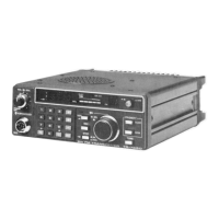
| Model | TR-7400A |
| Category | Transceiver |
| Language | English |