ADJUSTMENTS
3.6 Adjustment of PA Unit
(1) Connect the 50W wattmeter to the ANT terminal
(type MI.
(2) Connect the lead which connects the PA unit with
-tr~e TX unit to OUT of the TX unit.
(3)
Set the frequency to 146.0 MHz. Set the Hi/Low
switch to Hi.
(4)
Key the transmitter and adjust TC4 of the TX unit,
TCI, TC2, TC3 and TC4 of the PA unit for maxi-
mum indication.
Note
1:
VR3
of the PA unit shall be turned fully counterclock-
wise.
Note
2:
The maximum power shall be
28
W
or more.
(5) Set the frequency to 146.5
-
147.0 MHz, and adjust
TC2 for maximum power output. It should be done
to make the output at 147.9 MHz greater than that
at 144.9 MHz. Make sure of the difference in power
at 144.9 MHz and 147.9 MHz.
(6) The power should be 25
W or more at Hi in between
144.0 and 148.0 MHz.
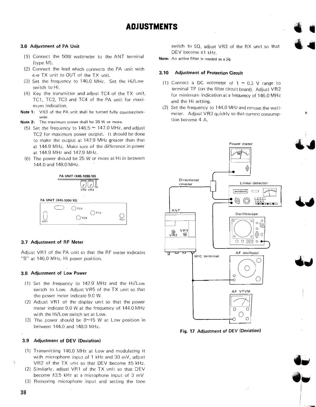
PA
UNlT 1x45-1090.10)
PA
UNlT (X45-1090-10)
I
1
3.7 Adjustment of RF Meter
Adjust VR1 of the PA unit so that the RF meter indicates
"8" at 146.0 MHz, Hi power position.
3.8 Adjustment of Low Power
(1) Set the frequency to 147.9 MHz and the Hi/Low
switch to Low. Adjust VR5 of the TX unit so that
the power meter indicate 9.0 W.
(2) Adjust
VR1 of the display unit so that the power
meter indicate 9.0 W at the frequency of 144.0 MHz
with the
HiILow switch set at Low.
(3) The power should
be
8-15 W at Low position in
between 144.0 and 148.0 NIHz.
3.9 Adjustment of DEV (Deviation)
switch to SQ, adjust VR3 of the RX unit so that
DEV become
+-I
kHz.
Note:
An active filter
IS
needed as a
jig.
3.10 Adjustment of Protection Circuit
(1) Connect a DC voltmeter of
1
-
0.3
V
range to
terminal TP (on the filter circuit board). Adjust VR2
for minimum indication at a frequency of 146.0 MHz
and the Hi setting.
(2) Set the frequency to 144.0 MHz and remove the watt-
meter. Adjust VR3 quickly so that current consump-
tion become 4 A.
Power meter
Directional
coupler Linear detector
llNT
I
Oscilloscope
AF
VTVM
I
Jq
Fig. 17 Adjustment of DEV (Deviation)
(1) Transmitting 146.0 MHz at Low and modulating it
with microphone input of 1 kHz and 30 mV, adjust
J
VR2 of the TX unit so that DEV become f5 kHz.
(2)
Similarly, adjust VR1 of the TX unit so that 3EV
become f3.5 kHz at a microphone input of 3 mV
(3) Removing microphone input and setting the tone