3. ADJUSTMENT
OF
TX UNlT
Techniciansshould be encouraged not to turn factory sealed
transformers but to check each stage for output.
3.1
Test Equipment Used
(1
)
Power source:
(2) Power meter
(3) Frequency counter
(4) Linear detector
(5) AG
(6)
RF VTVM
3.2
Adjustment of
10.7
MHz
(1) Setting
(a) Adjust frequency to 145.5 MHz and turn off the
repeater switch.
(b) Remove drive to final at "out" of TX
unit.
(2) Connect the frequency counter to
TPI of the TX
unit. Key the transmitter and adjust L3 so that it
read 10.700 MHz (10.7 MHz +200 Hz).
(3) Connecting the RF VTVM to the same TPI, adjust
L7 and L8 for maximurn indication.
The core of L7 should be in the center of the core.
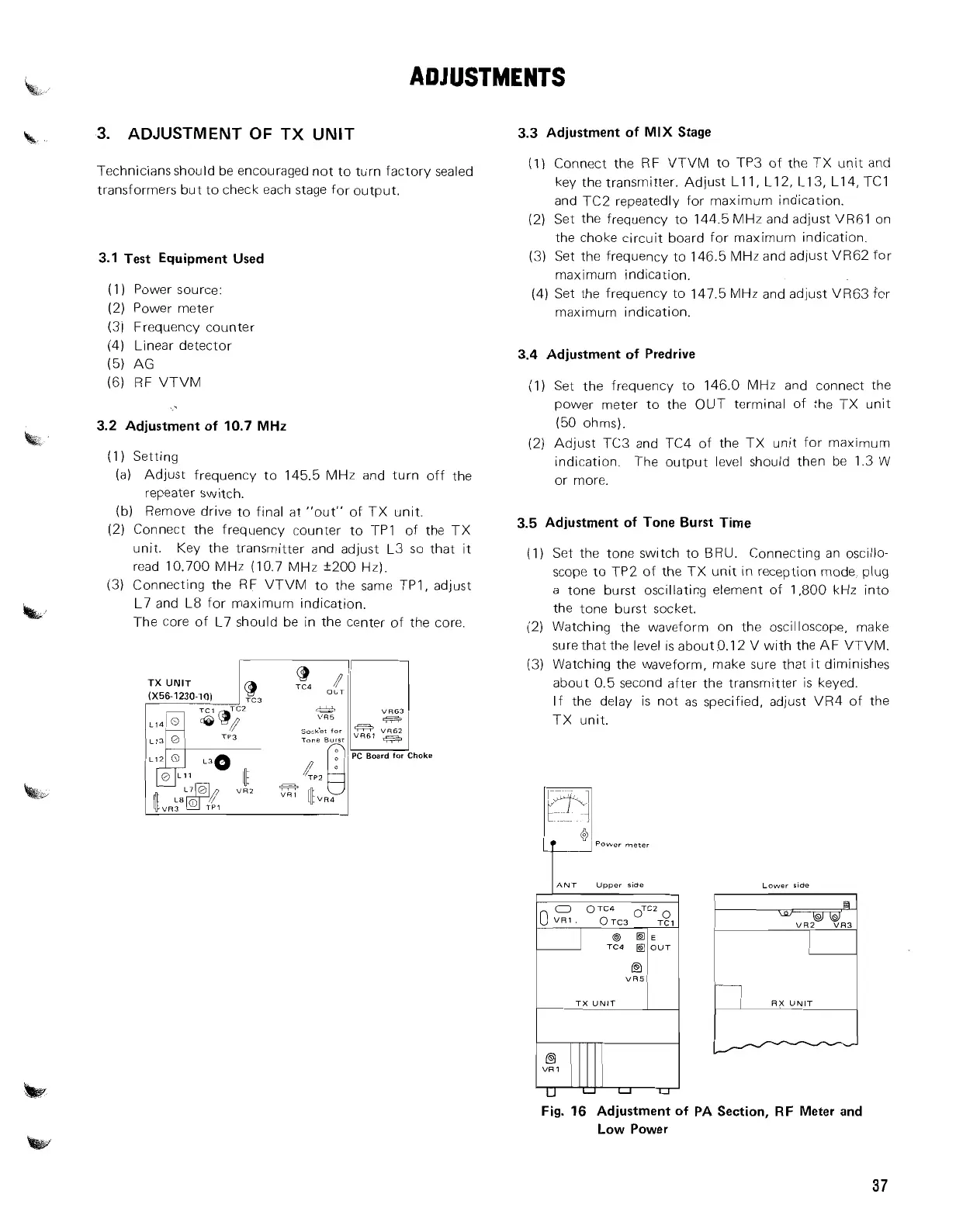
TX
UNlT
L13
0
soc&t
for
Tone
Burrr
PC Board
for
Choke
M
3.3
Adjustment of
MIX
Stage
(1)
Connect the RF VTVM to TP3 of the TX unit and
key the transmitter. Adjust Lll, L12, L13, L14, TCl
and TC2 repeatedly for maximum indication.
(2) Set the frequency to 144.5 MHz and adjust VR6l on
the choke circuit board for maximum indication.
(3) Set the frequency to 146.5 MHz and adjust VR62 for
maximum indication.
(4) Set the frequency to 147.5 MHz and adjust
VR63 for
maxlmum indication.
3.4
Adjustment of Predrive
(1) Set the frequency to 146.0 MHz and connect the
power meter to the OUT terminal of the TX unit
(50 ohms).
(2) Adjust TC3 and TC4 of the TX unit for maximum
indication. The output level should then be 1.3 W
or more.
3.5
Adjustment of Tone Burst Time
(1) Set the tone switch to BRU. Connecting an oscillo-
scope to TP2 of the TX unit in reception mode, plug
a tone burst oscillating element of 1,800 kHz into
the tone burst socket.
(2) Watching the waveform on the oscilloscope, make
surethatthe level is about.0.12 V with the AF VTVM.
(3) Watching the waveform, make sure that it diminishes
about 0.5 second after the transmitter is keyed.
If the delay
is not as specified, adjust VR4 of the
TX unit.
Lower side
VR5
TX
UNIT
RX
UNIT
Fig.
16
Adjustment of PA Section, RF Meter and
Low Power