Note
1:
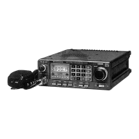
Adjust thecore of L1 so that the waveform
is
symmetrical.
Note
2:
The waveform should have three peaks.
Note
3:
Adjust carefully so that the waveform is symmetrical.
(4) Remove the wire used to ground terminal LE.
Note:
See "Adjustment of PLL". (1
1)
for the adjustment of L10.
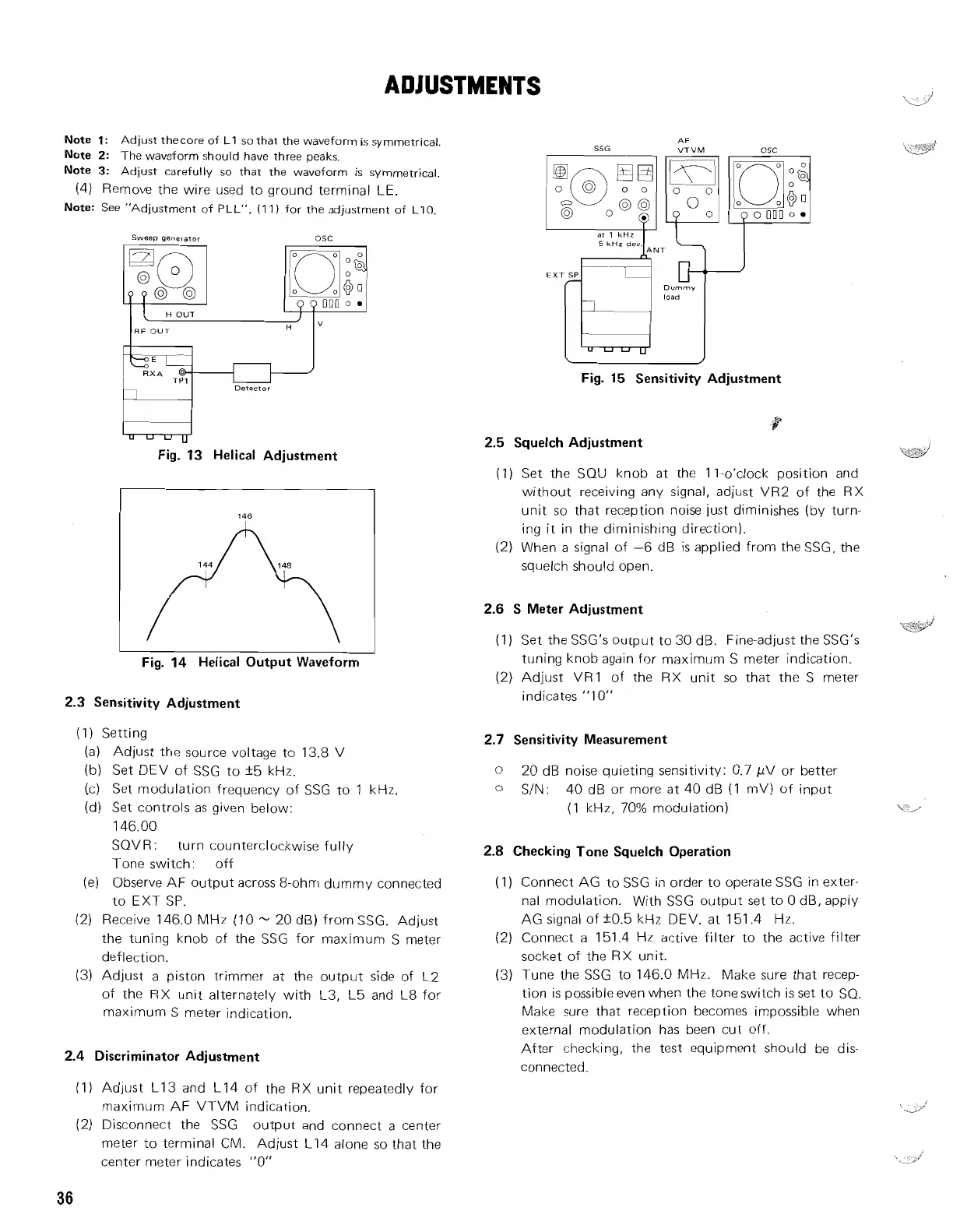
Fig. 13 Helical Adjustment
Sweep
generator
OSC
9
p
000
0
I
I
Fig. 14 Helical Output Waveform
H
OUT
RF
OUT
HI
I
L
2.3
Sensitivity Adjustment
"
(1) Setting
(a) Adjust the source voltage to 13.8 V
(b)
Set DEV of SSG to k5 kHz.
(.c) Set modulation frequency of SSG to 1 kHz.
(d) Set controls as given below:
146.00
SQVR
:
turn counterclockwise fully
Tone switch: off
(el
Observe AF output across 8-ohm dummy connected
to EXT SP.
(2)
Receive 146.0 MHz (10
--
20 dB) from SSG. Adjust
the tuning knob of the SSG for maximum S meter
deflection.
(3) Adjust a piston
trimmer at the output side of L2
of the RX unit alternately with L3, L5 and L8 for
maximum S meter indication.
2.4 Discriminator Adjustment
RXA
@
(1) Adjust L13 and L14 of the RX unit repeatedly for
maximum AF VTVM indication.
(2)
Disconnect the SSG output and connect a center
meter to terminal CM. Adjust L14 alone so that the
center meter indicates "0"
/
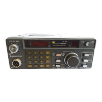
SSG
TP1
Detector
Dummy
t'
load
Fig. 15 Sensitivity Adjustment
2.5 Squelch Adjustment
(1) Set the SOU knob at the
I
I-o'clock position and
without receiving any signal, adjust VR2 of the RX
unit so that reception noise just diminishes (by turn-
ing it in the diminishing direction).
(2) When a signal of -6 dB is applied from the SSG, the
squelch should open.
2.6
S Meter Adjustment
.&JJ
(1)
Set the SSG's output to 30 dB. Fine-adjust the SSG's
tuning knob again for maximum S meter indication.
(2) Adjust
VR1 of the RX unit so that the S meter
indicates "1 0"
2.7 Sensitivity Measurement
0
20 dB noise qu~eting sensltlvlty: 0.7 pV or better
0
SIN 40 dB or more at 40 dB (1 mV) of Input
(1 kHz, 70% modulat~on)
\,-
,
2.8
Checking Tone Squelch Operation
(1) Connect AG to SSG in order to operate SSG in exter-
nal modulation. With SSG output set to 0 dB, apply
AG signal of k0.5 kHz DEV. at 151.4 Hz.
(2)
Connect a
151.4 Hz active filter to the active filter
socket of the RX unit.
(3)
Tune the
SSG
to 146.0 MHz. Make sure that recep-
tion is possible even when the tone switch is set to SO.
Make sure that reception becomes impossible when
external modulation has been cut off.
After checking, the test equipment should be dis-
connected.