(3) Connect the VTVM to terminal TP2 and adjust the
core of L10 180' counterclockwise from the point
where oscillation begins.
RF voltage of TP2
=
0.7
-
1 V
(4) Adjust the core of L11 so that the RF voltage across
terminal TPI is maximum.
RF voltage at TPI
=
0.1 5
-
0.3V
(5)
Adjust the core of L11 so that the RF voltage at
terminal PI is maximum, and then readjust the core
of L4. RF voltageat PI
=
1 -2V
(6) Adjust TC1 so that the DC voltage terminal CV is
5 v.
Note:
The
PLL
will work properly after steps
(1)
-
(6)
and the
unlock indicator on the panel will go off.
(7) Adjust the core of
L15 so that the RF voltage at
terminal LR is maximum.
RF voltage at LR
=
0.3
-
1 V
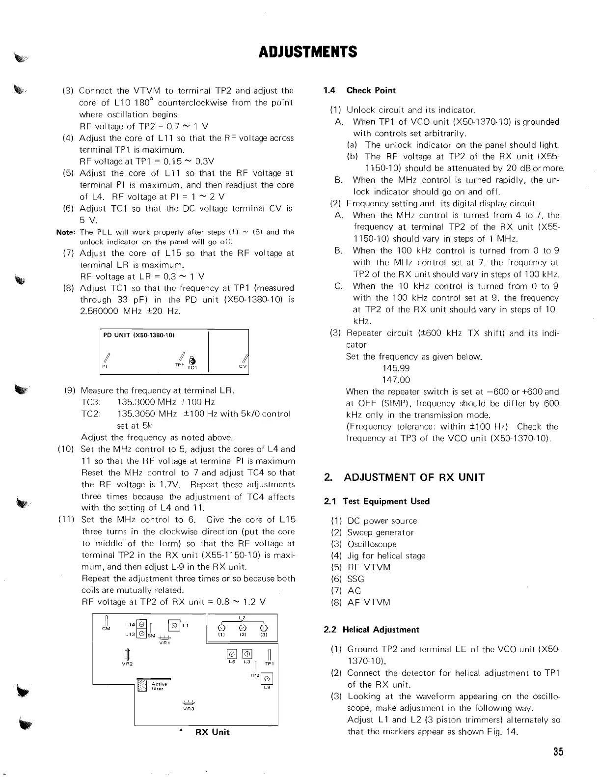
(8) Adjust TC1 so that the frequency at TPI (measured
through 33 pF) in the PD unit (X50-1380-10) is
2.560000 MHz f20 Hz.
(9) Measure the frequency at terminal LR.
TC3: 135.3000 MHz
"00 Hz
TC2: 135.3050 MHz +I00 Hz with 5k/0 control
set at 5k
Adjust the frequency as noted above.
(10) Set the MHz control to 5, adjust the cores of L4 and
11 so that the RF voltage at terminal PI is maximum
Reset the
NlHz control to 7 and adjust TC4 so that
the RF voltage is 1.7V. Repeat these adjustments
three times because the adjustment of TC4 affects
with the setting of L4 and 11.
(1 1) Set the MHz control to 6. Give the core of L15
three turns in the clockwise direction (put the core
to middle' of the form) so that the RF voltage at
terminal TP2 in the RX unit (X55-I 150-10) is maxi-
mum, and then adjust L-9 in the RX unit.
Repeat the adjustment three times or so because both
coils are mutually related.
RF voltage at
TP2 of RX unit
=
0.8
-
1.2 V
I
VRl
111
L5
L3
1
TPl
I
"
RX
Unit
1.4 Check
Point
(1) Unlock circuit and its indicator.
A. When TPI of VCO unit (X50-1370-10) is grounded
with controls set arbitrarily.
(a) The unlock indicator on the panel should light.
(b) The RF voltage at TP2 of the RX unit (X55-
1150-10) should be attenuated by 20 dB or more.
B. When the MHz control is turned rapidly, the un-
lock indicator should go on and off.
(2) Frequency setting and its digital display circuit
A.
When the MHz control is turned from 4 to 7, the
frequency at terminal TP2 of the RX unit (X55-
1150-10) should vary in steps of 1 MHz.
B. When the 100 kHz control is turned from 0 to 9
with the MHz control set at 7, the frequency at
TP2 of the RX unit should vary in steps of 100 kHz.
C. When the 10 kHz control is turned from 0 to 9
with the 100 kHz control set at 9, the frequency
at TP2 of the RX unit should vary in steps of 10
kHz.
(3) Repeater circuit (f600 kHz TX shift) and its indi-
cator
Set the frequency as given below.
145.99
147.00
When the repeater switch is set at -600 or
+600 and
at OFF (SIMP), frequency should be differ by 600
kHz only in the transmission mode.
(Frequency tolerance: within +-I00 Hz) Check the
frequency at TP3 of the VCO unit (X50-I 370-10).
2.
ADJUSTMENT
OF
RX
UNIT
2.1 Test Equipment Used
(1
)
DC power source
(2) Sweep generator
(3) Oscilloscope
(4) Jig for helical stage
(5) RF VTVM
(6) SSG
(7) AG
(8) AF VTVM
2.2 Helical Adjustment
(1) Ground
TP2 and terminal LE of the VCO unit (X50-
1370-1 0).
(2) Connect the detector for helical adjustment to TPI
of the RX unit.
(3) Looking at the waveform appearing on the oscillo-
scope, make adjustment in the following way.
Adjust
L1 and L2 (3 piston trimmers) alternately so
that the markers appear as shown Fig. 14.
3
5