DISASSEMBLY
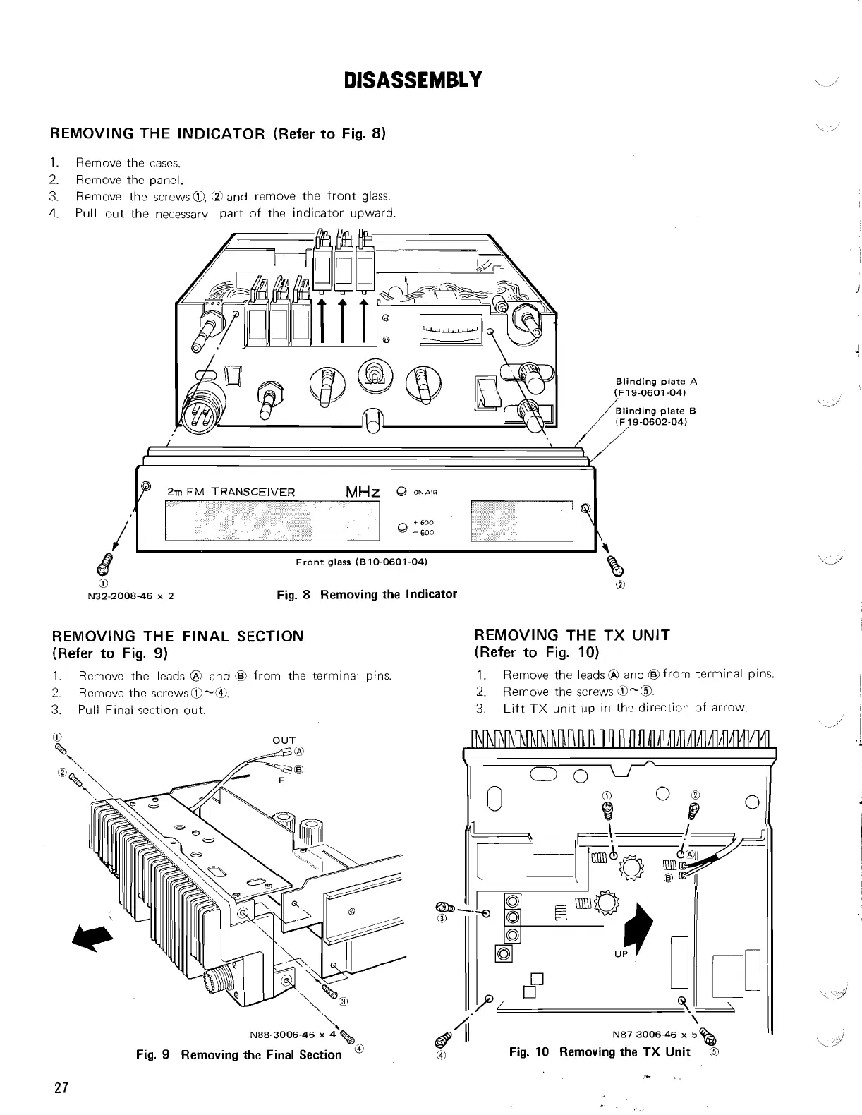
REMOVING THE INDICATOR (Refer
to
Fig.
8)
1.
Remove the cases.
2.
Remove the panel.
3.
Remove the screws@, @and remove the front glass.
4.
Pull out the necessary part of the indicator upward.
Blinding plate
A
(F19-0601-04)
/
Blinding plate
B
(F 19-0602-04)
,r
FM
TRANSCEIVER
MHz
,
00~~1~
+600
,
,
0
-600
Front glass (810-0601-04)
REMOVING THE FINAL SECTION
(Refer
to
Fig.
9)
Fig.
8
Removing the Indicator
0
REMOVING THE TX UNIT
(Refer
to
Fig.
10)
1.
Rernove the leads
@
and
@
from the terminal pins.
1.
Remove the leads
@
and @from terminal pins.
2.
Remove the screws@-W.
2.
Remove the screws
0-0.
3.
Pull F~nal section out.
3.
Lift TX unit
up
in the direction of arrow.
?
OUT
'.
N88-3006-46
x
4
%
Fig.
9
Removing the Final Section
&
\
N87-3006-46
x
5
%3
Fig.
10
Removing the
TX
Unit
O
0
-.