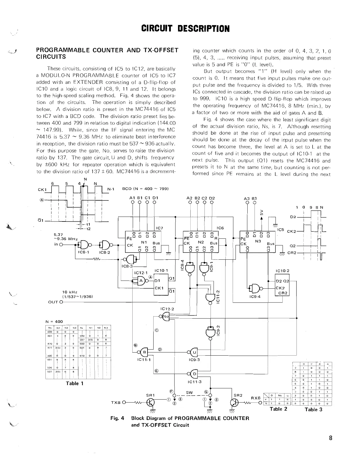
PROGRAMMABLE COUNTER AND TX-OFFSET
ing counter which counts in the order of 0, 4, 3, 2,
1,
0
CIRCUITS
(5), 4, 3,
.....
receiving input pulses, assuming that preset
These circuits, consisting of IC5 to IC12, are basically
a MODULO-N PROGRAMMABLE counter of IC5 to IC7
added with an EXTENDER consisting of a D-flip-flop of
lClO and a logic circuit of IC8, 9,
I I
and 12.
It belongs
to the high-speed scaling method. Fig. 4 shows the opera-
tion of the circuits. The operation is simply described
below.
A division ratio is preset in the
MC74416 of IC5
to IC7 with a BCD code. The division ratio preset lies be-
tween 400 and 799 in relation to digital indication (144.00
-
147.99). While, since the IF signal entering the MC
74416 is 5.37
-
9.36 MHz to eliminate beat interference
in reception, the division ratio must be 537
-
936 actually.
For this purpose the gate, No, serves to raise the division
ratio by 137.
The gate circuit,
U
and D, shifts
frequency
by
f600
kHz
for repeater operation which is equivalent
to the div~sion ratio of 137
f
60. MC74416 is a decrement-
value is 5 and
PE
is "0" (L level).
But output becomes "1" (H level) only when the
count is 0. It means that five input pulses make one out-
put pulse and the frequency is divided to 115. With three
ICs connected in cascade, the division ratio can be raised up
to 999. IClO is a high speed D-flip-flop which improves
the operating frequency of MC74416,
8
MHz (min.), by
a factor of two or more with the aid of gates A and
B.
Fig. 4 shows the case where the least significant digit
of the actual division ratio, Ns, is 7.
Although resetting
should be done at the rise of input pulse and presetting
should be done at the decay of the input pulse when the
count has become three, the level at A
is
set to L at the
count of five and it becomes the output of IC10-1 at the
next pulse. This output (01) resets the MC74416 and
presets it to N at the same time, but counting is not per-
formed since PE remains at the L level during the next
Fig.
4
Block Diagram of PROGRAMMABLE COUNTER
and TX-OFFSET Circuit