Do you have a question about the KEPCO BOP 50-20MG and is the answer not in the manual?
Provides critical safety precautions, symbols, and warnings for operating the power supply.
Emphasizes the criticality of interconnections between power source, supply, and load for optimum performance.
Covers local, national, and international safety rules for grounding the instrument's metal cover and case.
Explains connecting source power via a three-wire input power and mating connector.
Addresses grounding schemes to avoid ground loops and minimize noise effects on the output circuit.
Stresses the importance of a single earth-ground point and warns against multiple ground points.
Guides connecting the load and setting up for local operation, referencing power supply basics.
Details enabling a fail-safe/interlock feature requiring disassembly and modification by authorized personnel.
Guides connecting the GPIB connector and configuring the unit for remote operation via SCPI commands.
Guides connecting the RS 232 connector and configuring the unit for remote operation via SCPI commands.
Guides connecting the LAN interface and configuring the unit for remote operation via SCPI commands.
Explains configuring LAN parameters like Host Name, IP Address, Subnet Mask via the web interface.
Details parallel, series, and parallel-series configurations to increase voltage and current range.
Provides instructions for connecting units in parallel or series, including master/slave configuration.
Explains configuring protection to ensure a fault shuts down all interconnected power supplies.
Guides the configuration of units for parallel, series, 2x2, or 3x2 combinations, including master/slave roles.
Details the power-up sequence for multiple unit combinations, including order and system stages.
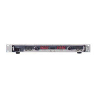
Provides instructions on how to turn the power supply ON using the front panel circuit breaker.
Guides on highlighting parameters, pressing keys to modify, and using the ADJUST control or keypad for changes.
Details setting passwords for Main Unit, Admin 1, and Admin 2 to protect settings and prevent tampering.
Explains how to access protected menus by entering the correct password.
Describes operating the BOP power supply from the front panel using the keypad and ADJUST knob.
Explains how the unit defaults to Local mode and how to unlock the keypad if a remote command was received.
Guides selecting the main channel mode (Voltage or Current) using the MODE key.
Explains programming settable voltage/current parameters and associated protect limits.
Describes configuring protection limits to be displayed and changed as a single value or independent settings.
Describes reducing allowable voltage and current settings from nominal using the Max/Min Settings menu.
Details adjusting software limits for main channels (+Voltage Max, –Voltage Min, etc.) for user-defined values.
Explains establishing software limits for output voltage and current protection.
Explains disabling (OFF) or enabling (ON) the output using the STANDBY key or SCPI commands.
Guides on changing default settings that are in effect each time the unit is turned on.
Explains storing and recalling power supply settings, including mode, reference, protection, and output status.
Advises performing steps to avoid unexpected voltages or currents when accessing waveforms.
Details creating a new waveform by entering type, name, protection, count, and segment parameters.
Guides on executing a waveform after saving it, including stopping execution and managing states.
Explains the reset function which executes a power-on sequence to reset settings and clear LIST entries.
Explains shutting down a standalone unit or multiple configurations using remote signals to the PROTECTION EXT. PORT.
Explains programming the operating mode (voltage or current) externally via the Analog I/O port.
Details how protection limits are determined by four analog signals applied to the Analog I/O Port.
Advises reducing mode change evaluations and programming only active parameters for better response.
Describes configuring interface ports (GPIB, RS 232, LAN) for remote requirements.
Details configuring the GPIB port, including address, language, and device clear settings.
Guides on changing the GPIB address from the default value.
Details setting up the RS 232C Serial port for communication using SCPI commands.
Guides on changing the Baud Rate configuration for the serial port.
Outlines setup required for the BOP 1KW-ME to communicate via the LAN interface using SCPI commands.
Details setting the IP address manually or automatically via DHCP or AUTO IP.
Details remote programming via LAN using a standard web browser connected to the internet.
Explains configuring LAN parameters like Host Name, IP Address, Subnet Mask via the web interface.
Describes operating the unit by clicking the OPERATE INSTRUMENT box and modifying settings via the web interface.
Outlines the primary adjustment means using CAL:DATA commands for fine and coarse adjustments.
Provides a step-by-step procedure for complete unit calibration using SCPI commands.
Details the calibration process using front panel keys and screens.
Provides step-by-step instructions for performing calibration using local mode.
| Power Rating | 1000 W |
|---|---|
| Type | Bipolar Operational Power Supply |
| Ripple Voltage | 1 mVrms |
| Cooling | Forced air |
| Output Voltage | 0-50V |
| Output Current | 0 to 20 A |
| Control Interface | IEEE-488, RS-232 |
| Source Voltage | 50/60 Hz |
| Operating Temperature | 0 to 40 °C |
| Relative Humidity | 0-90% non-condensing |
| Dimensions | 483mm x 133mm x 445mm |