EN
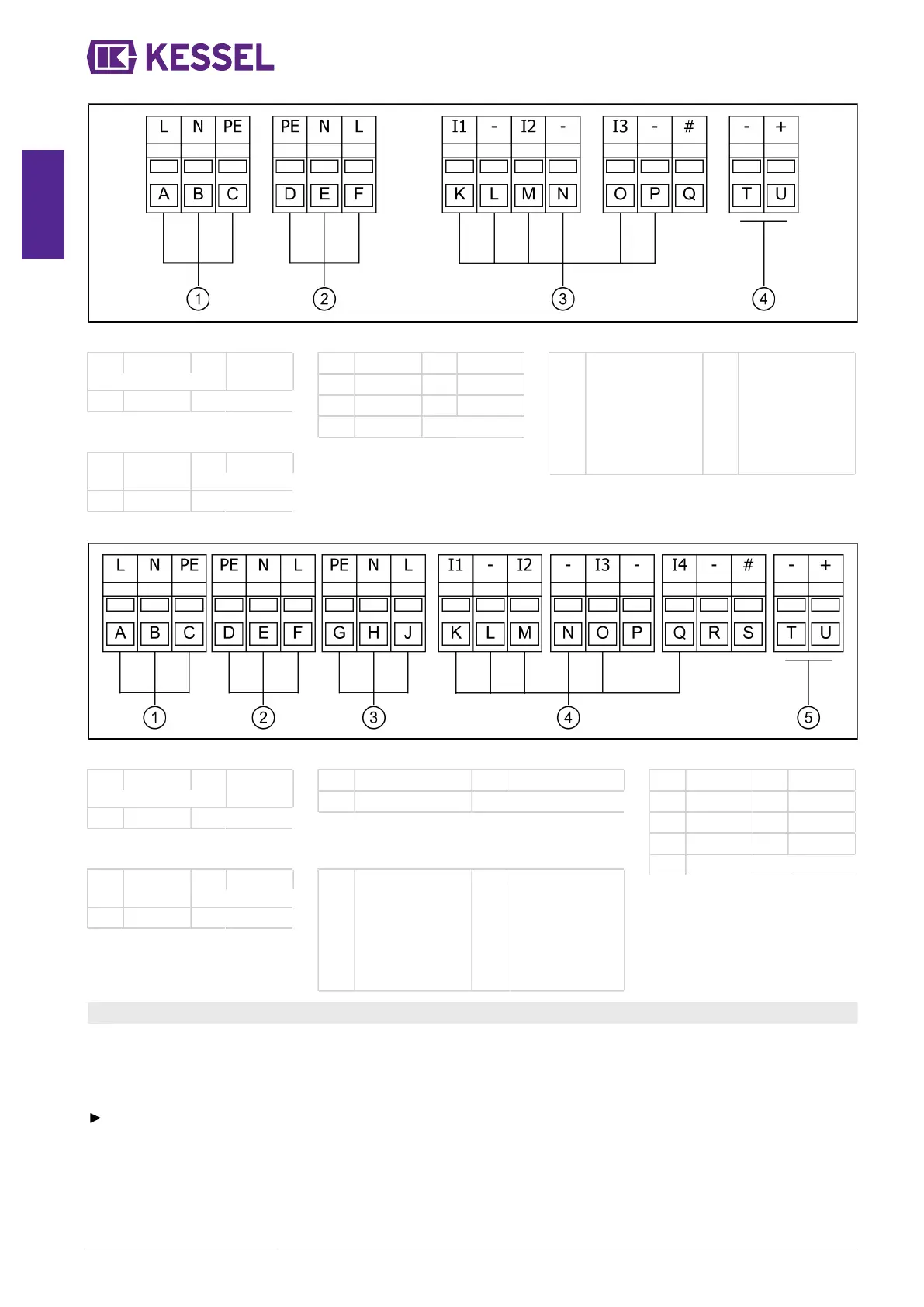
Connection diagram (Mono)
(1) Voltage
(A) Brown (C) Green/
yellow
(B) Blue
(2) Wastewater pump
(D) Green/
yellow
(F) Brown
(E) Blue
(3) Float switch
(K) Yellow (O) Grey
(L) White (P) Green
(M) Pink (Q) Not used
(N) Brown
(4) Alarm
(T) Connection for
external remote
signal genera-
tor/potential-free
contact (option-
ally retrofittable
Art.No. 80074)
(U) Connection for
external remote
signal genera-
tor/potential-free
contact (option-
ally retrofittable
Art.No. 80074)
Connection diagram (Duo Tronic)
(1) Voltage
(A) Brown (C) Green/
yellow
(B) Blue
(3) Wastewater pump (Duo)
(G) Green/yellow (J) Brown
(H) Blue
(2) Wastewater pump
(D) Green/
yellow
(F) Brown
(E) Blue
(5) Alarm
(T) Connection for
external remote
signal genera-
tor/potential-free
contact (option-
ally retrofittable
Art.No. 80074)
(U) Connection for
external remote
signal genera-
tor/potential-free
contact (option-
ally retrofittable
Art.No. 80074)
(4) Float switch
(K) Yellow (P) Not used
(L) White (Q) Green
(M) Pink (R) Not used
(N) Brown (S) Not used
(O) Grey
4.10 Mount the accessory parts
The terminal block "Alarm" has been preset for connection of the audible alarm unit. If a potential-free contact is to be used,
the terminal block must be cleared for this (see "Potential-free contact" section).
Prepare housing and cable duct (as explained in Chap. (see "Connecting the probe"). Use the outside right cable duct.
Remote signal generator
Connect the remote signal generator (art. no. 20162) as shown on the connection diagram.
30 / 116 016-233_01