INSTALLATION
Keston Combi - Installation and Servicing
3G9560
N
L
N
FROST
STAT
(
OPTIONAL
)
ROOM
STAT/
TIMER
Room
Stat or
Prog.
Room
Stat
Optional
Frost Stat
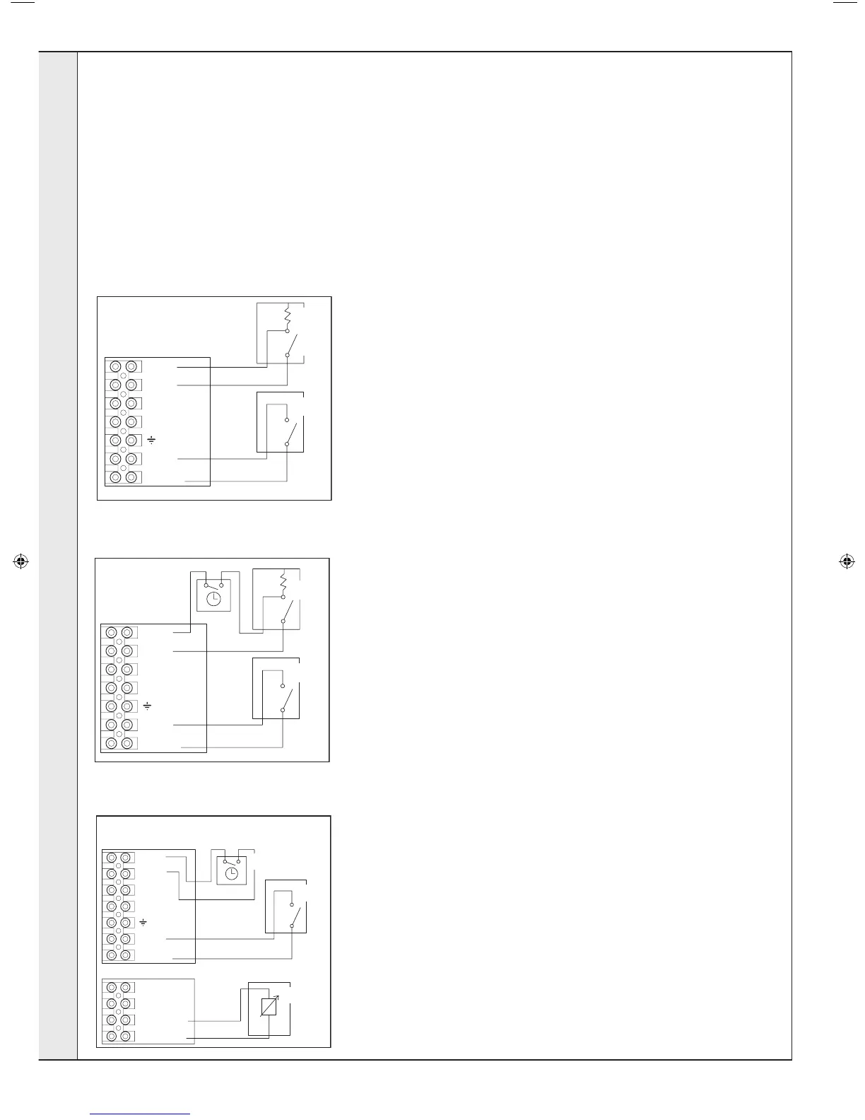
DIAGRAM A
Internal Timer or
Programmable Room Stat
3G9561
N
L
N
FROST
STAT
(
OPTIONAL
)
ROOM
STAT/
TIMER
Room
Stat
Optional
Frost Stat
DIAGRAM B
External
Timer
Keston offer 2 kits as follows:
(see individual kits for installation instructions)
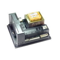
Electronic Timer (7 day) kit - 7 day electronic CH timer ts into the control box of the boiler. This can be tted in conjunction
with a room thermostat. Features English language installation help messages.
25
INTERNAL WIRING.... CONT’D
(1) ROOM THERMOSTAT WITH INTERNAL BOILER TIMER OR
(2) PROGRAMMABLE ROOM THERMOSTAT
1. Remove link wire between room stat/timer terminals.
2. Connect room stat across terminals as shown in diagram A
3. If room stat has a neutral connection, connect this to terminal
N (load) in the fused spur.
3G9707a
L
N
FROST
STAT
(
OPTIONAL)
ROOM
STAT/
TIMER
OpenTherm
Harness
Weather
Compensation
Optional
Frost Stat
Outside
Sensor
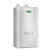
DIAGRAM C
Weather Compensation Kit
Timer
ROOM THERMOSTAT + TIMER
1. Remove link wire between room stat/timer terminals.
2. Connect room stat and programmer in series as shown in diagram B.
3. If room stat has a neutral connection, connect this to terminal N (load) in the
fused spur.
FROST THERMOSTAT
If parts of the system are vulnerable to freezing or the programmer is likely to be
left off during cold weather, a frost stat should be tted in conjunction with a pipe
thermostat.
1. Position the frost thermostat in a suitable position, i.e. area vulnerable to
freezing.
2. Connect frost stat across terminals marked frost stat shown in diagrams A &
B.
WEATHER COMPENSATION KIT
The two wires from the weather compensation kit (outside
sensor), must be connected into the two right hand terminals as
shown in diagram C.
INSTALLATION
207895-2.indd 26 02/01/2013 09:38:28