INSTALLATION
Keston Combi - Installation and Servicing
WARNING. Whilst effecting the required gas tightness test and purging air from the gas installation,
open all windows and doors, extinguish naked lights and DO NOT SMOKE.
A. Electrical Installation
1. Checks to ensure electrical safety should be carried out by a
competent person.
2. ALWAYS carry out the preliminary electrical system checks,
i.e. earth continuity, polarity, resistance to earth and short
circuit, using a suitable test meter.
B. Gas Installation
1. The whole of the gas installation, including the meter,
should be inspected and tested for tightness and purged in
accordance with the recommendations of BS. 6891.
In IE refer to IS.813:2002.
2. Purge air from the gas installation by the approved methods
only.
31
COMMISSIONING AND TESTING
GENERAL
Please Note: The combustion for this appliance has
been checked, adjusted and preset at the factory for
operation on the gas type dened on the appliance
data plate. No measurement of the combustion is
necessary. DO NOT adjust the air/gas ratio valve.
Having checked:
- That the boiler has been installed in accordance
with these instructions.
- The integrity of the ue system and the ue seals,
as described in the Flue Installation section.
Proceed to put the boiler into operation as follows:
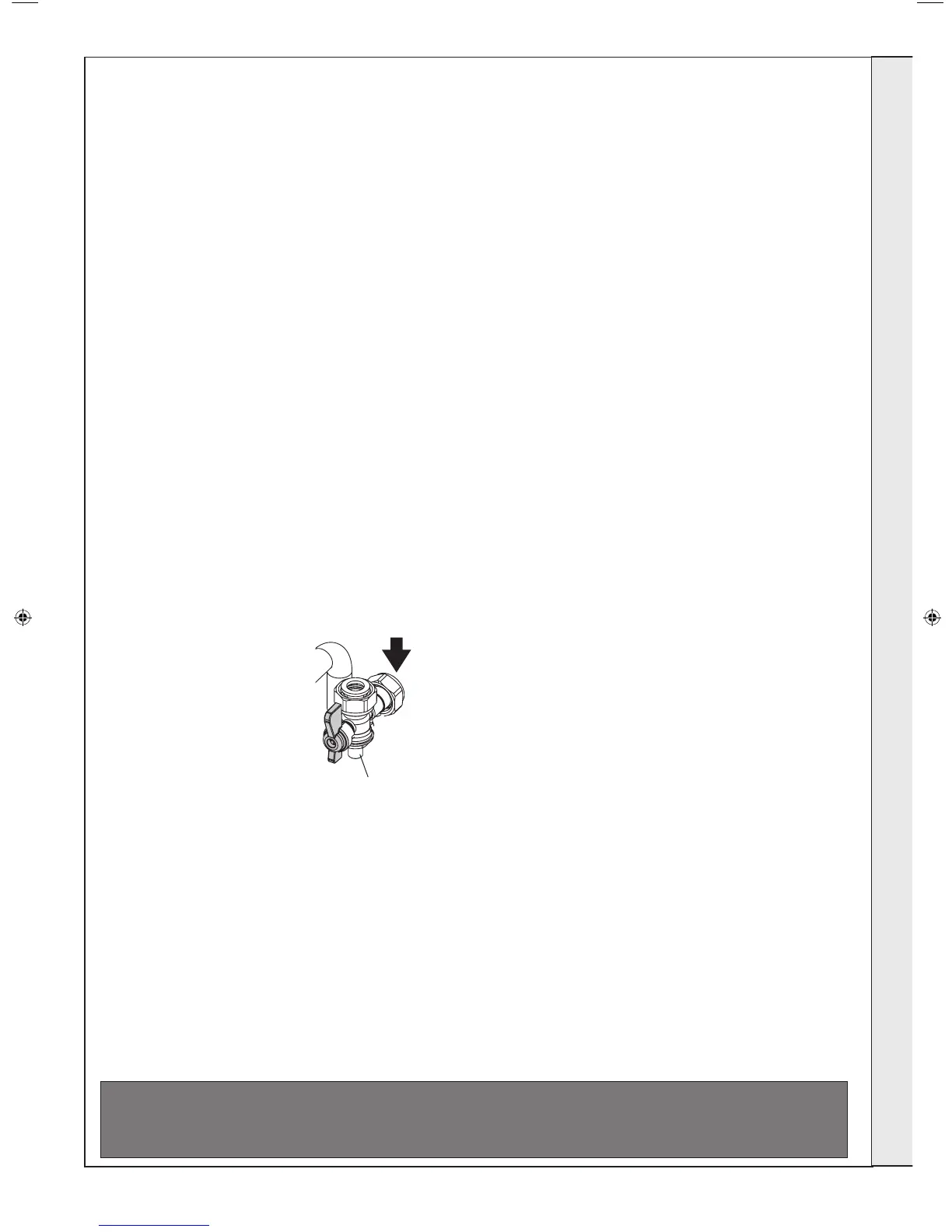
CHECK THE OPERATIONAL (WORKING) GAS
INLET PRESSURE
Set up the boiler to operate at maximum rate by
opening hot tap to maximum
ow.
With the boiler operating in
the maximum rate condition
check that the operational
(working) gas pressure at
the inlet gas pressure test
point complies with the
requirements - refer to “Gas
Supply” on page 8.
Ensure that this inlet pressure
can be obtained with all other
gas appliances in the property
working.
Safety
Drain
Valve
Black
Handle
Yellow
Handle
Black
Handle
Blue
Handle
3G9927a
CH Flow
DHW Outlet
Gas Supply
CH Return
DHW Inlet
Gas Pressure
Test Point
ATTENTION !
IT IS A CONDITION OF THE MANUFACTURERS WARRANTY THAT THE BENCHMARK
COMMISSIONING CHECKLIST IS FULLY COMPLETED AND LEFT WITH THE APPLIANCE
“SERVICE REQUIRED” Function
When the boiler has been installed for more than 1 year the following
message will appear on the screen:
“12 Month Service Interval Request”
To cancel this message move the CH Temperature Control Knob away
from the maximum position. Then move the knob to the maximum
position, away from the maximum position and back into the maximum
position again within 3s.
“Service Mode” will be shown on the screen, this will disappear after
5 mins.
“AIR VENTING” Function
The Air Venting function should not be required for this boiler.
• The Air Venting function operates for 5 mins as follows:
• Pump On for 50s, Pump Off for 10s (repeats 5 times)
• Diverter valve in hot water position for 30s then CH position for
30s (repeats 5 times)
• The function ends automatically.
To activate the Air Venting function proceed as follows:
Turn the DHW temperature control knob fully anti-clockwise.
Turn the CH ow temperature control knob fully anti-clockwise.
Turn and hold the Mode Knob in the Reset position for more than 5s
and then turn it to the Winter or Summer position
The boiler will display “Installer Mode”
If no faults have occurred the boiler will display “No Faults”
If any faults have occurred a list of faults up to a maximum of 10
including the type of fault and how long ago it occurred will be shown.
The boiler will then display the current values of ow temperature,
return temperature, domestic hot water temperature, DHW ow rate
and diverter valve position.
Next the boiler will display
“Venting Boiler OFF” - “For Activation change Pre-heat Mode”
Now move the pre-heat knob and the Air Venting Function will begin,
the boiler will display:
“Venting Boiler Off” - “Pump and Diverter Valve Cycling” -
Duration 5 mins” - “Reset to End”
INSTALLATION
207895-2.indd 31 02/01/2013 09:38:31