57
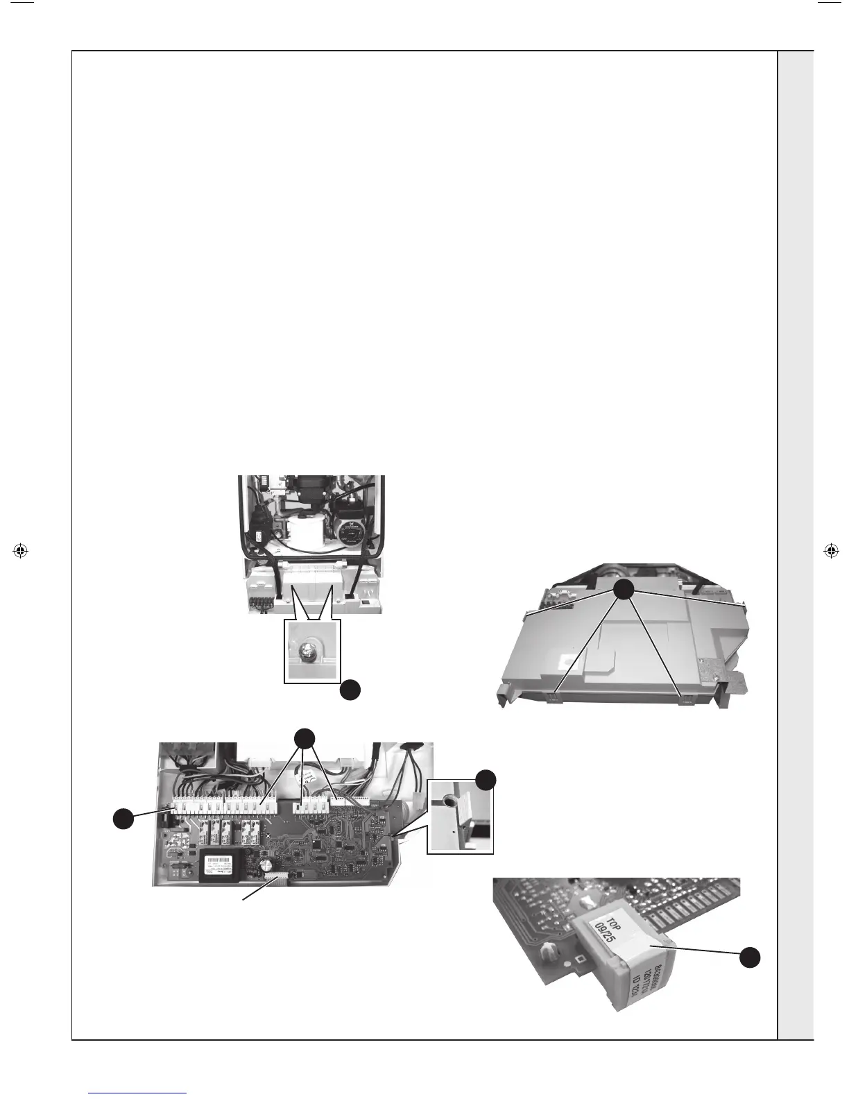
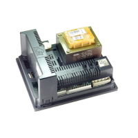
MAIN PCB REPLACEMENT
Note. Fit the earth strap provided with the PCB to your wrist and secure to a suitable earth on the boiler chassis.
3
4
6
5
Plastic
Clip
5
7
Ribbon Cable Connection
8. Re-connect all plug connections.
9. Reassemble in reverse order.
10. Turn power back on to the boiler, after a few moments the
display will start alternating between “c” and “0”. Turn the
reset knob fully clockwise and when the display shows “ - ”
turn the knob fully anti-clockwise IMMEDIATELY.
Finally move the knob into the required position (Standby,
Summer or Winter).
11. Check operation of the boiler. Refer to Frame 36.
1. Refer to Frame 45.
2. Note the control knob positions.
3. Remove the 2 screws retaining the control box cover.
4. Carefully lift the 4 retaining clips and remove control box
cover.
5. Unplug all lead connections to the PCB including the ribbon
cable (to facilitate ribbon cable removal, ease side clips
apart and pull upwards), also where applicable, push the
small plastic clip with an electrical screwdriver to facilitate
plug removal.
6. Spring out the two side retaining clips and pull the PCB
upwards to clear the 4 corner retaining posts.
7. Take the new Primary PCB and attach the appropriate Boiler
Chip Card (BCC).
Note. Ensure the correct orientation of BCC by placing
“TOP” side up as shown.
SERVICING
207895-2.indd 47 02/01/2013 09:38:43