Do you have a question about the Ketotek KT4000 and is the answer not in the manual?
Describes the KT4000 as an easy-to-use, reliable dual relay output temperature controller for electric appliances.
Features an acrylic panel, plastic-steel shell, and controls both heater and cooler for temperature adjustment.
Offers one setpoint and one differential for very easy setup and operation.
Includes alarms for exceeding temperature limits or sensor errors, and autosaves settings on power loss.
Details power supply (110Vac), temperature control range (-19.9~199.9°F), and return difference (1.0~30°F).
Specifies ±1°F accuracy, 0.1°F resolution, and NTC waterproof sensor (2m/6.56ft).
States the output relay contact capacity is 16A at 100-240Vac.
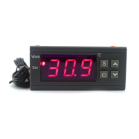
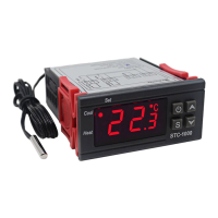
Shows product images and provides dimensions for the control panel and socket.
Explains indicator lights and describes normal operation, setting parameters, and saving settings.
Details how to restore factory defaults and lists code table functions, ranges, and defaults.
Provides basic and advanced setting examples for temperature control, including delays and alarms.
Explains the logic for cooler and heater activation/deactivation based on temperature setpoints (LS, Ld).
Describes the function of the cooling delay output (PL) where the cooler does not work immediately.
Details how high (AH) and low (AL) temperature limits trigger alarms and stop outputs.
Explains how to use the CA value to calibrate the measured temperature against the actual temperature.
Addresses error codes HHH (short circuit) and LLL (open circuit) for the temperature sensor.
Warns about keeping the controller away from water and recommends power limits for different load types.
Outlines the 12-month warranty period and commitments for defective products (repair, replace, refund).
The KT4000 is a user-friendly and dependable dual-relay output temperature controller designed for automatic temperature control in various electrical appliances. It features an acrylic panel and a plastic-steel socket shell, allowing it to control both heating and cooling elements to maintain a desired temperature. The device simplifies temperature management with a single setpoint and differential, making it very easy to configure. Additionally, it includes an alarm function that activates when the temperature exceeds predefined limits or if a sensor error occurs. All program settings are automatically saved even after a power down, ensuring continuous operation without loss of configuration.
In its normal operating state, the screen displays the real-time temperature detected by the sensor. A single press of the "SET" button will show the temperature set value (LS), and another press will display the differential value (Ld). To conserve energy, the screen backlight automatically turns off after 10 minutes of inactivity.
For more advanced configuration, pressing and holding the "SET" button for 3 seconds enters the setting parameter mode, where the screen displays "LS." Users can adjust the "LS" value using the "UP" or "DOWN" buttons. Subsequent presses of "SET" will cycle through other parameters like "Ld," allowing for further adjustments. This method is used to set all code values from "LS" to "CA" as listed in the code table. Once all settings are complete, pressing and holding "SET" for 3 seconds saves the configuration and returns the device to its normal display. If no button is pressed for 30 seconds after entering the setting mode, the system will not save any modified parameters and will revert to the previous settings.
The KT4000 also offers a convenient way to restore factory default settings. In normal working status, simultaneously pressing the "UP" and "DOWN" buttons for 3 seconds will display "FF" on the screen, indicating that all code values have been reset to their default factory settings.
The device provides clear visual indicators for its operational status. A "COOL" indicator light illuminates when the cooling socket is active, supplying power to a cooler. If this light flashes, it signifies a delay in the cooling output. Similarly, a "HEAT" indicator light turns on when the heating socket is active, providing power to a heater. An "ALARM" indicator flashes, accompanied by a buzzer, when the temperature exceeds the alarm high limit (AH) or falls below the alarm low limit (AL), or in the event of a sensor error.
For basic setup, consider an example where the thermostat is used to control the temperature of a reptile incubator, with the heating socket connected to a light and the cooling socket connected to a fan. In this scenario, only the "LS" (temperature set value) needs to be set, for instance, to 80°F, with no other parameters requiring adjustment. Under these settings, the fan will activate when the temperature reaches 84°F or higher and stop when it drops below 80°F. Conversely, the light will turn on when the temperature falls below 76°F and turn off when it reaches 80°F or higher.
For advanced settings, after setting the desired "LS" temperature, users can configure "Ld" (differential value), "PL" (cooling delay output), "AH" (alarm high limit), "AL" (alarm low limit), and "CA" (temperature calibration). It's important to ensure that "AH" is greater than "LS + Ld" and "AL" is less than "LS - Ld" for proper operation.
The cooling delay output (PL) feature is particularly useful. If "PL" is set, the cooler will not activate immediately in cooling mode. Instead, the "COOL" indicator will flash, and the cooler will delay its operation by the specified "PL" time.
The alarm high/low limit settings (AH, AL) provide an essential safety feature. If the measured temperature reaches or exceeds "AH," a high-temperature alarm will be triggered, with the buzzer sounding and the "ALARM" indicator flashing. This alarm will persist until the temperature drops below "AH" or any key is pressed. Similarly, if the measured temperature falls to or below "AL," a low-temperature alarm will activate, with the buzzer and flashing "ALARM" indicator continuing until the temperature rises above "AL" or a key is pressed.
The temperature calibration (CA) function allows users to correct any discrepancies between the measured temperature and the actual temperature. By setting a "CA" value, the device can align the displayed temperature with the true temperature, where the corrected temperature equals the measured temperature plus "CA."
Regarding maintenance and troubleshooting, if the heater or cooler fails to activate when the specified temperature is reached, users should check the "Ld" value, verify the sensor placement, and ensure that "PL" is not set, as a delay in cooling output could be the cause. If the screen displays "HHH" or "LLL," it indicates a sensor issue. "HHH" signifies a short circuit in the temperature sensor, while "LLL" indicates an open circuit. In either case, the buzzer will alarm with a flashing "ALARM" indicator, which cannot be stopped by pressing any key. The solution is to inspect or replace the sensor.
It is crucial to note that while the sensor probe is waterproof, the controller itself is not. Therefore, the controller should be kept away from water. To ensure optimal performance and prevent overloading, each output socket utilizes a high-quality 16A relay. For resistive loads such as heating rods, heating pads, or electric water heaters, the maximum recommended power is 1100W. For inductive loads like compressors or pumps, the maximum recommended power is 275W.
The product comes with a 12-month warranty from the date of purchase. In the event of a defect due to qualified product problems, the company commits to repair, replace, or refund the device. For technical support or customer service, users can contact info@cnketotek.com.
| Display Color | Red |
|---|---|
| Control Output | Relay Output |
| Display | LED |
| Control Accuracy | 0.1°C |
| Power Supply | AC 110V-220V |
| Control Algorithm | PID |