Do you have a question about the Kettler Golf C2 and is the answer not in the manual?
Guidelines on user age limits and necessary supervision for equipment use.
Essential safety warnings regarding power, batteries, usage, and potential hazards.
Details conformity to DIN EN ISO 20957 standards and therapeutic use suitability.
Recommendations for a secure and hazard-free assembly process.
Advice on proper equipment use, cleaning, and basic upkeep.
Information on ordering spare parts and environmentally sound disposal methods.
Itemized list of components included for models 07689-200, 07689-400, 07689-450/650.
Itemized list of components included for models 07689-600, 07689-800/880/900.
Identifies items not supplied with the product packaging.
Instructions for assembling the initial base structure of the exercise bike.
Guide for attaching the steering column to the main unit.
Details for connecting major frame sections with specified hardware and torque.
Further instructions for securing frame components with hardware.
Instructions for assembling the support structure for the handlebars.
Guide for installing handlebars on the 07689-900 C12 model.
Additional steps for fitting handlebars on the 07689-900 C12 model.
Instructions for a specific handlebar mounting setup.
Instructions for an alternative handlebar mounting setup.
Final steps to ensure the handlebars are firmly attached.
Guide for attaching a specific bracket component.
Guide for attaching a specific mounting component.
Instructions for installing the main console or display unit.
Connecting the display unit to the main console or wiring.
Routing and connecting electrical wires within the handlebar assembly.
Completing the electrical connections for the handlebars.
Guide for fitting and adjusting the seat post height.
Instructions for securely attaching the seat to the seat post.
Recommendation to warm pedal straps in water for easier installation.
Guide for fitting the pedals onto the crank arms.
Preparing the straps for mounting the bottle holder.
Instructions for attaching the bottle holder to the frame.
Final steps to firmly secure the bottle holder.
Visual guide for adjusting the handlebar for optimal user comfort and control.
Visual guide for adjusting the seat for ergonomic training.
Overview of how to use the console and its various functions.
Step-by-step instructions for changing the batteries in the computer display.
Information on proper disposal of batteries and environmental considerations.
Detailed steps for detaching the pedal arms from the unit.
Lists tools and parts, some not included, needed for pedal arm removal.
Critical advice to use only supplied or genuine KETTLER power adapters for safety.
Visual guide identifying numbered components for ordering.
Table linking part numbers to specific models C2, C4, and S4.
Comprehensive list of part numbers and their corresponding item numbers for C2, C4, S4 models.
Visual guide identifying numbered components for C6 and S6 models.
Comprehensive list of part numbers and their corresponding item numbers for C6 and S6 models.
Visual guide identifying numbered components for C8, C10, and C12 models.
Comprehensive list of part numbers and their corresponding item numbers for C8, C10, C12 models.
| Type | Exercise Bike |
|---|---|
| Brand | Kettler |
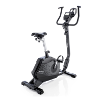
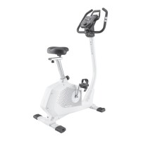
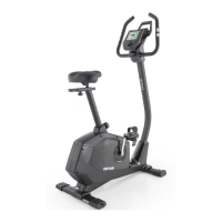
| Model | Golf C2 |
| Resistance System | Magnetic |
| Max User Weight | 130 kg |
| Weight Capacity | 130 kg |
| Display | LCD |
| Heart Rate Monitor | Hand Grip Sensors |
| Material | Steel |
| Features | Adjustable Seat, Transport Wheels |