Installation Instructions
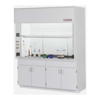
Supreme Air LV Bench Hood
Fume Hood w/Auto-return Sash
K
ewaunee Scientific Corporation • P.O. Box 1842 • Statesville, North Carolina 28687-1842 • Phone 704-873-7202
IILV05-SA 06/05-3
Packing List
Preparation
1. Place, level, and install the Base Unit Assembly that will support the Fume Hood as shown on page 4.
2. Attach the Fume Hood Worksurface to the Base Unit Assembly at the corners using epoxy cement or similar adhesive.
Worksurface should be centered on units and overhang the front by 1/2". Worksurface must be level.
Shim as needed. Top should extend all the way to rear wall.
3. Uncrate Fume Hood taking care to sort and inventory all parts.
4. Remove End Panels from Fume Hood (by lifting up and out) and remove screws anchoring Weight Box to Fume Hood.
5. Remove all packing from
Fume Hood and any tape holding parts in place for shipping.
Fume Hood is packed fully assembled except for Lower Airfoil. The Top Front Panel, may be
removed (by lifting up and out) to fit through narrow doorways and/or for easier access.
Generally electrical fixtures and plumbing fittings are shipped installed, but may be shipped loose
depending on job requirements. Fittings may also be pre-wired and/or pre-piped. Fixtures are not
shown on assembly diagram as quantities and locations vary to meet individual requirements.
Installation
6. Check that Sash Belts are properly routed over front pulleys, and engage rear pully sprockets.
7. Check sash auto-sash return height and adjust as needed. (See Auto-return Adjustment Instructions on page 5)
Handle Frameless Sash with care - Laminated Saf
ety Glass will crack if abused.
9. Using as many workers as needed, lift assembled Fume Hood and place on leveled Worksurface being careful not to spread
bottom of hood.
Make sure hood is pushed back as far as possible and centered on
Base Unit Assemb
ly
.
Check
End P
anels
f
or
plumb and square.
10. Attach
Lower Airfow
to the Worksurface
and Fume Hood using the included hardware as shown in Detail 1. Check that
Lower
Airfoil is straight and level.
11.
Coordinate connections of service fittings, electrical fixtures, and ductwork with the respective trades (i.e. mechanical, electrical,
HVAC). After connections are complete, replace interior Access Panels, if removed, and the exterior End Panels.
12.
Check
Sash again f
or level, smooth movement, and auto-return. Adjust as needed.
To level, loosen the two (2) set screws on one of the rear Sash Pulleys (see Figure 2), level sash, then retighten set screws.
13.
Inspect the complete installation, remove any dust, dirt, or other debris. Check all moving parts for proper operation, and adjust
or lubricate as necessary.
Rear Baffles ma
y be removed for cleaning by removing the two Baffle StandoffKnobs and lifting up
and out on the baffle panels.
On Pallet Fume Hood
Hardware Package (taped to side of hood)
Lower Airfoil (on top of hood)
Fume Hood Worksurface is packaged separately.
Hardware Package
(4-7) 10-24 x 3/4" Phillips Truss Head Machine Screw
see detail 1 with Nut and Flat Washer
(2) #8 x 1/2" Sheet Metal Screws
(1) Installation Instructions


 To Next Page
 Loading...
