Continuity
(resistance) tests
10
this is cancelled you will know because the Ω symbol will not flash.
CAUTION - before taking any measurements always check the leads
have been zeroed.
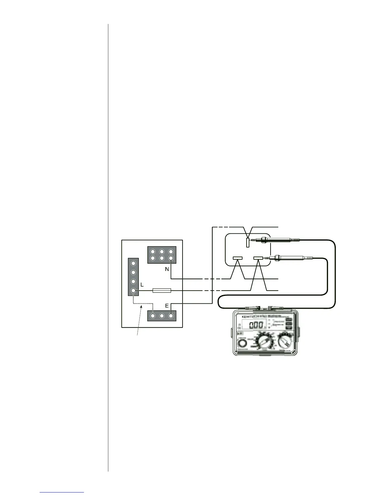
5 Connect the test leads to the circuit whose resistance is required (see
Fig 3 for a typical connection arrangement), having first made sure
that the circuit is not live. Note that the live circuit warning lamp
will illuminate if the circuit is live - but check first anyway!
6Press the test button and read the circuit resistance from the display.
The reading will have the test lead resistance already subtracted if the
Continuity null function has been used.
7 Note that if the circuit resistance is greater than 20Ω the instrument
will autorange to the 200Ω, if it is greater than 200Ω it will autorange
to the 2000Ω range.
Note: If the reading is greater than 2000Ω the overange symbol
‘OL’ will remain displayed.
The KT62 is provided with a facility to change the polarity of the test
current used by the instrument during continuity tests. To use this function
proceed as follows:-
1Perform a continuity test as outlined in the procedures above.
2Operate the polarity switch if required.
3Repeat the continuity tests and the polarity of the test current will be
reversed.
Temporary link
Test at socket
between L and E
Fig 3