4 Continuity
(resistance) tests
9
Warning: Ensure that circuits to be tested are not live.
Disconnect the instrument from the circuit under test before
operating the function switch.
To select the low resistance range select ‘CONTINUITY’.
4.1 Instrument layout - see Fig 1 on page 3.
4.2 Test Procedure
The object of continuity testing is to measure only the resistance of the
parts of the wiring system under test. This measurement should not
include the resistance of any test leads used. The resistance of the test
leads needs to be subtracted from any continuity measurement. The KT62
is provided with a continuity null feature which allows automatic
compensation for any test lead resistance.
You should only use the test leads supplied with the instrument.
Proceed as follows:-
1 Select the continuity test by rotating the function dial.
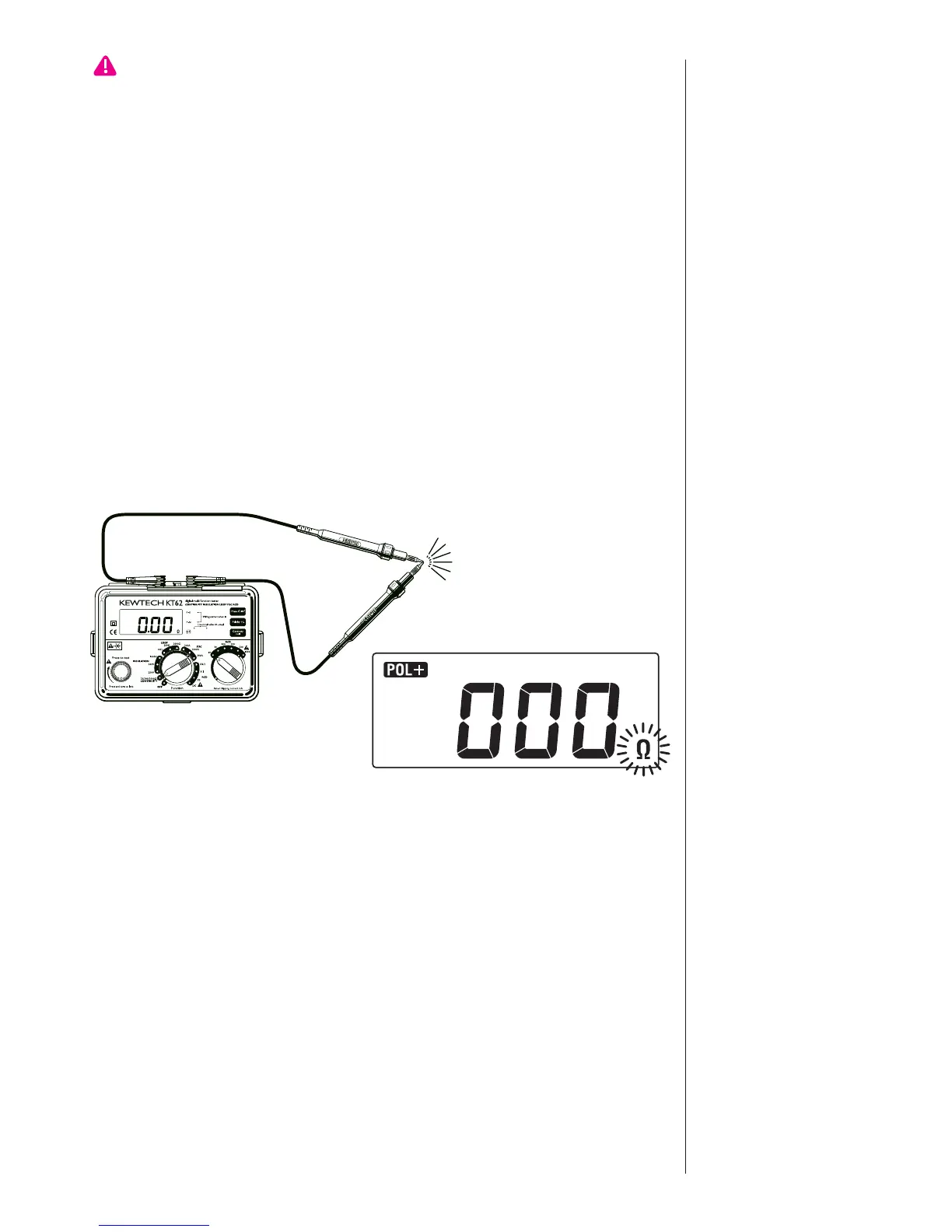
2 Connect the ends of the test leads firmly together (see Fig 2) and press
and lock down the test button. The value of the lead resistance will be
displayed.
3 Operate the Continuity Null button, this will null out the lead
resistance and the indicated reading should go to zero.
4Release the test button. Press the test button and ensure the display
reads zero before proceeding. While using the Continuity null function,
the Ω symbol will flash. The null value will be stored even if the
function switch is turned to the OFF position. This memorized null
value can be cancelled by disconnecting the test leads and pushing the
Continuity Null button with the test button pressed or locked. When
Fig. 2