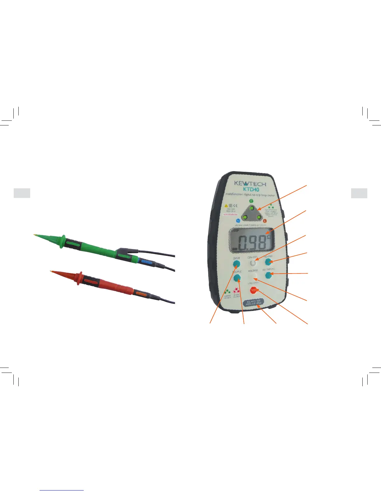
Test lead configuration
Lead configuration for High Current 2-wire testing with TLI feature
TheTLI(TrueLoopImpedence)functionisintendedforuseatdistributionboardsand
similarpointswhereyouaremeasuringonthesupplysideofanySwitch/RCDgear.
TheTLImeasurementfunctionisselectedbypressingbutton9labelled‘Ze/DB’.This
functionusesthemaximumhighcurrentofthetesterandrequirestheuseofthe
distributionboardleadsetconguredin2-wiremode.Donotusethisfunctionwiththe
mainsleadorthedistributionleadsetin3-wiremode.
Toarrangethetestleadsin2-wiremodepulltheblueprodoffthebluetestleadand
plugtheexposed4mmconnectorintothebackofthegreenconnectorasshownbelow.
YouwillnowhavetheEarthandNeutralleadsconnectedtogetherreadyforconnection
totheEarthorNeutralconductortobetested.
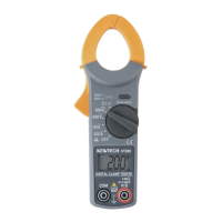
Operation – a Detailed View of the KTD40
2 ThreeLEDsshow
socket wiring
status
4 LCD-default
L-Nvoltage
measurement
1 On/Offbutton
5 No-triploopselect
(default)
7 No-tripPFC
(prospectivefault
current)
6 Pushtostarttest
9 Highcurrent
loop impedance
test
8 Voltageselect
L-N(default)L-E
andN-E
3 PolarityTest
10 Highcurrent
PFCtest