2
Checking the Package Contents
Before using the unit, confirm that the parts and equipment listed below are included in the
package of the model you purchased.
Sensor amplifier
z DIN rail mount type
z Panel mount type
Sensor head
We have thoroughly inspected the package contents before shipment. However, in the event
of defective or broken items, please contact your nearest KEYENCE office.
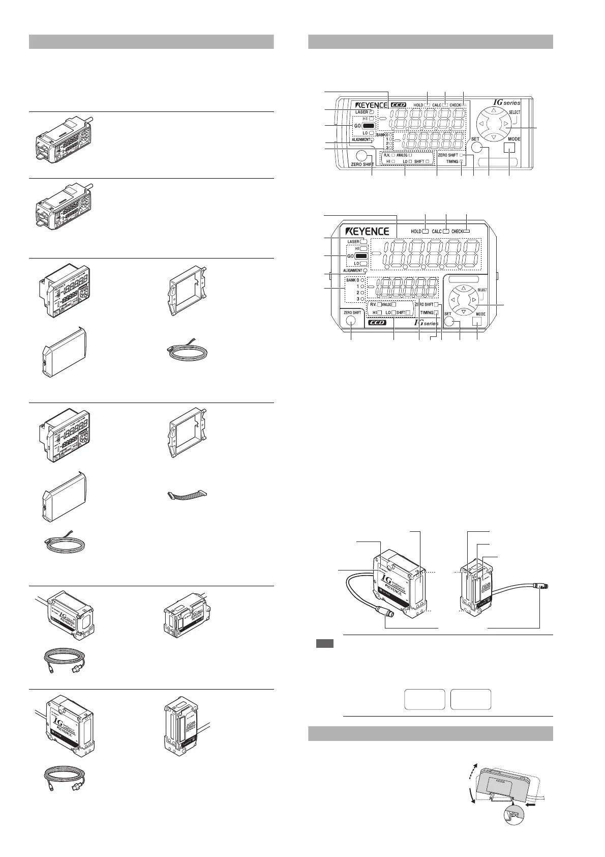
Part names
Sensor amplifier
z DIN rail mount type (IG-1000/IG-1050)
z Panel mount type (IG-1500/IG-1550)
(1) Main display
(2) Laser emission indicator [LASER]
(3) Judgment indicator [HI / GO / LO]
(4) Optical axis alignment indicator [ALIGNMENT]
(5) Bank indicator [BANK 0 to 3]
(6) Zero shift button [ZERO SHIFT]
(7) Sub display identification indicator [R.V. / ANALOG / HI / LO / SHIFT]
(8) Sub display
(9) Timing input indicator [TIMING]
(10)Zero shift indicator [ZERO SHIFT]
(11)SET button [SET]
(12)MODE button [MODE]
(13) Arrow buttons
(14) Check indicator [CHECK]
(15) Calculation indicator [CALC]
(16)Hold indicator [HOLD]
Sensor head
Mounting the Amplifier
DIN rail mount type, main unit (IG-1000)
Align the claw at the bottom of the main body with the
DIN rail. While pushing the main body in the direction
of the arrow (1), tilt the amplifier in the direction of the
arrow (2).
To remove the amplifier, raise the main body in the
direction of the arrow (3) while pushing it in the
direction of the arrow (1).
IG-1000 (main unit)
Amplifier x 1 Instruction manual x 1
IG-1050 (expansion unit)
Amplifier x 1
IG-1500 (main unit)
Amplifier x 1
Panel mounting
tool
x 1
Front protection
cover
x 1
Power/Input-
output cable (2 m)
x 1
(Number of cable
cores: 12)
Instruction manual x 1
IG-1550 (expansion unit)
Amplifier x 1
Panel mounting
tool
×1
Front protection
cover
×1
Expansion cable
(50 mm) x 1
Input-output cable
(2 m) x 1
(Number of cable
cores: 8)
IG-010 (10 mm width)
Transmitter (T) x 1 Receiver (R) x 1
Sensor head
connection cable
(2 m)
x 2
IG-028 (28 mm width)
Transmitter (T) x 1 Receiver (R) x 1
Sensor head
connection cable
(2 m)
x 2
Note
Use the transmitter and receiver in combination with the same serial
number. If they are used in combination with different serial numbers, the
operation and accuracy are not guaranteed. The serial number is located on
top of the transmitter and receiver.
(11) (12)(10)(6)
(16) (15) (14)
(1)
(2)
(3)
(4)
(5)
(7) (8) (9)
(13)
(11) (12)(10)(6)
(16) (15) (14)
(1)
(2)
(3)
(4)
(5)
(7) (8) (9)
(13)
Optical axis
alignment
indicator
Optical axis
alignment
indicator
Power
indicator
Position monitor
Laser transmitter
Laser Receiver
Connector
Transmitter Receiver
Top
Bottom
SERIAL No.
12345678
Transmitter
No.
12345678
Receiver
(1)
(2)
(3)
 Loading...