Red: Indicates the
received light position
Green: Indicates
the measurement
position
The position monitor on the IG Series sensors
makes it possible to visually check how a
target is detected. The user can prevent
mounting or setting errors by observing the
red lights that indicate the received light
position and the green lights that indicate the
measurement position.
Extremely easy to use due to the built-in position monitor
Determining the Part of a Target to be Measured
Optical axis alignment in
progress
Easier Optical Axis Alignment
The position monitor makes it easier to align
the optical axis. Easily perform optical axis
alignment by adjusting the sensor head so
that all of the position monitor lights turn red.
Optical axis alignment
complete
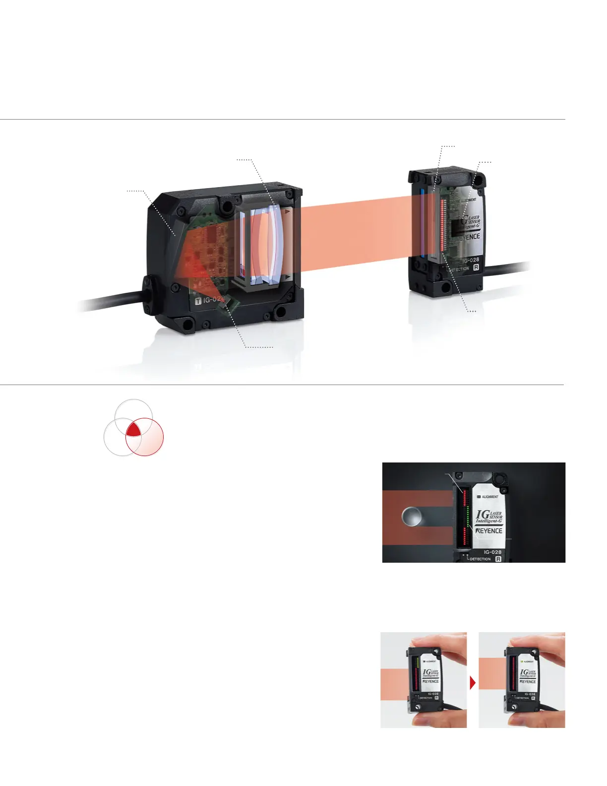
Mechanism that realizes high stability
and accuracy
Reflecting mirror
Parallel light lens
Multi-wavelength laser
Position monitor
I-DSP
L- CC D
Transmitter
Receiver
5
SERIES
Intelligent
Rugged
Easy
I