About the Reset Function
During the NETCOM6P programming procedures, you are prompted to reset the device,
which is a soft re-boot. This is equivalent to a power cycle.
Steps to Install and Program the NETCOM6P
The NETCOM6P plugs directly into the CIM that is to be designated as CIM 0.
For programming the NETCOM6P (required), use a direct serial connection via the COM2
terminal block on CIM 0 as instructed. Also ensure you place jumpers ON J12 during the
programming procedure when instructed.
As an option, the NETCOMP can be programmed off-site before installation providing you
have a 12 VDC power supply that can be connected to the CIM’s TB4 power terminal. See
Figure 6 or Figure 8.
Steps to Install and Program the NETCOM6P… cont’d
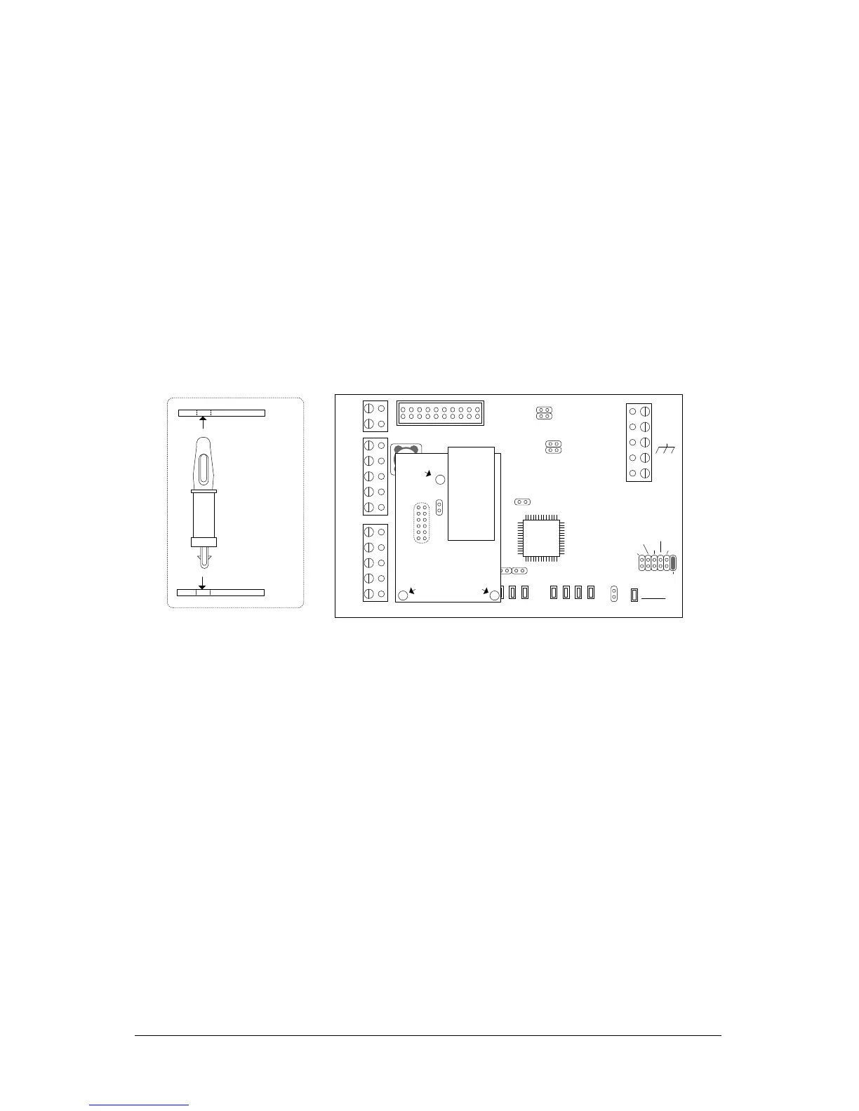
1. Mount the NETCOM6P into SCKT1 on CIM 0 in the correct orientation as shown below.
Do not change the orientation of the standoffs.
2. Mount the CIM/NETCOM6P in its designated location in the metal enclosure.
3. On the CIM circuit board, place a jumper on J12.
4. Connect the ribbon cable from the HDR1 terminal on the CIM circuit board to the H2
terminal on the control board. The H2 terminal provides power for programming the
NETCOM6P.
5. Ensure the control board has power.
6. If the control board is newly installed and this is the first time it is powered up,
restore the factory defaults as outlined depending on the version of PC109x control
board:
J16 Jumpers - place a jumper ON J16—pin H, then momentarily place a jumper
ON J1—Clear Memory to load the factory defaults. Allow approximately 2
minutes and do not make any changes while the control board re-configures.
Remove the jumper from J16—pin H
S1 and S3 Switches – After applying power, press S1, wait 5 seconds, and then
press S3 within 10 seconds to load the factory defaults. Allow approximately 2
minutes and do not make any changes while the control board re-configures.
7. Connect the RS-232 serial cable from the laptop or PC to the COM2 terminal block on
the CIM circuit board. See Figure 5 or Figure 7.
8. Turn on the laptop or PC connected to the CIM circuit board.
9. Select start > All Programs and select Keyscan NETCOM Program Tool from the
Keyscan menu.
 Loading...