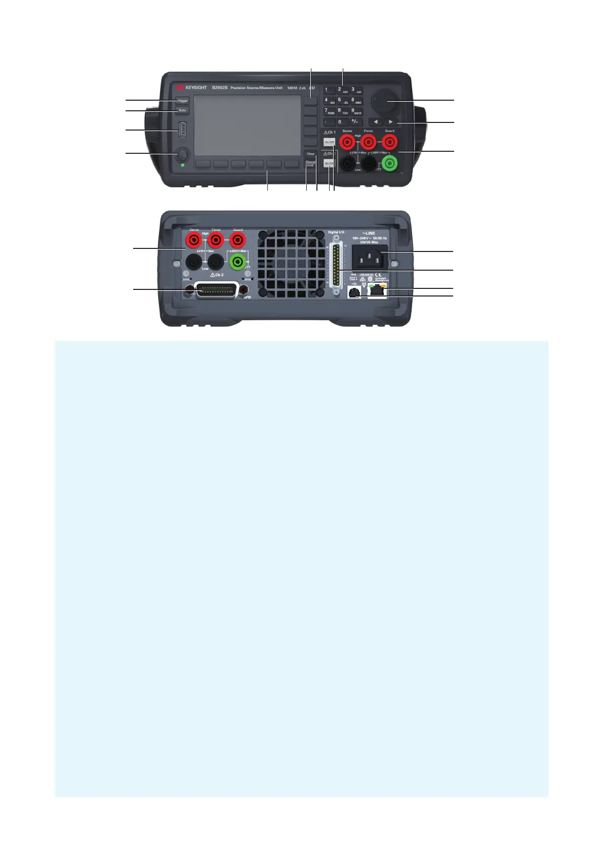
1. Line switch: Turns the instrument on or off.
2. USB-A connector: Used to connect a USB memory.
3. Auto key: Starts a repeat measurement or aborts the repeat measurement.
4. Trigger key: Starts a single measurement, aborts a repeat measurement, or initiates trigger system.
5. Assist keys: Five keys for setup assistance. Mode, Source, Limit, Measure, More, etc.
6. Numeric/alpha keys: Used to enter the value of setup parameters specified by the field pointer.
7. Rotary knob:
In MOVE (blue) status: Turning it moves the field pointer. Pressing it fixes the pointer position.
In EDIT (green) status: Turning it changes the field pointer parameter value. Pressing it fixes the value.
8. Left and right keys:
In MOVE (blue) status: Moves the field pointer.
In EDIT (green) status: Changes the field pointer parameter value. If the field pointer is on a numeric
value entry field, pressing the key changes the pointer to a digit pointer.
9. Channel 1 terminals: High Force, Low Force, High Sense, Low Sense, Guard, and chassis ground
10. On/Off switch(es): Used to enable or disable the channel. Turns the channel off if it is in the output status
even if it is in the remote status. Two switches on 2-channel models. The switch turns green if the channel
is enabled. The switch turns red if the channel is in the high voltage state.
11. View key: Changes the display mode.
12. Cancel/Local key:
Cancels the setup operation if the instrument is in the local status.
Returns the instrument to the local status if it is in the remote status.
13. Function keys: Six keys for detail setup of several functions. Config, Function, Trigger, Result, File, Program,
I/O, System, and More.
14. Channel 2 terminals: Only on 2-channel models.
15. GPIB interface connector: Connects to GPIB interface of an external computer or equipment.
16. USB-B connector: Connects to USB interface.
17. LAN interface connector: Connects to 10/100 Base-T interface. Left LED indicates activity. Right LED
indicates link integrity.
18. Digital I/O connector: D-sub 25 pin female connector for general purpose I/O (GPIO). For trigger input/
output, interface to a handler, interface to an interlock circuit, etc. If the interlock terminals are open, the
instrument output is limited to ±42 V.
19. AC input connector: AC power cord is connected to this receptacle.
1
3
5 6
7
9
12 1113
14
10
2
8
4
15
14
16
19
18
17