Keysight 34921A-34925A User’s Guide 45
Lifetime of relays is severely degraded as current or voltage goes up.
If higher voltage is being switched, limits on source current are recommended.
When the power is off, all channel and Analog Bus relays open.
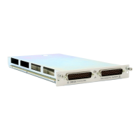
Two-Wire Mode
You may configure the 34923A as:
– two independent 20-channel 2-wire MUXes. This configuration requires
neither the use of external wiring nor connection through the internal Analog
Buses.
– one 40-channel, 2-wire MUX. For this configuration, you must use external
wiring or connect through the internal Analog Buses.
In 2-wire mode, you can close no more than 20 channels simultaneously due to
power dissipation. These 20 channels are split 10 to a bank. However, note that
Analog Bus relays count half as much as channel relays in that total. For example,
with one Analog Bus relay closed, you can close up to a maximum of 19 channel
relays. If you try to close more than the allowed number of channels, you will
receive an error message.
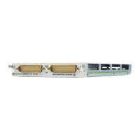
Four-Wire Mode
You may configure the 34923A as a 20-channel 4-wire MUX. This configuration
requires neither external wiring nor connection through the Analog Buses.
For 4-wire resistance measurements, the instrument automatically pairs channel
n on Bank 1 (source) with channel n+20 on Bank 2 (sense) to provide these
connections. Four-wire controls occur only when doing 4-wire measurement
operations through the internal DMM, such as MEASure:FRESistance? or
scanning a channel previously configured as 4-wire.
Because user-attached reactive loads and backplane parasitic capacitance
may result in high in-rush currents, 100
in-rush resistors protect the reed
relays from damage and performance degradation. Therefore, you must
consider these resistors when you are designing a measurement. Refer to the
simplified schematics on page 47 and page 53.